
RECONFIGURING THE FLOW3 BETWEEN NORMALLY CLOSED AND NORMALLY OPEN
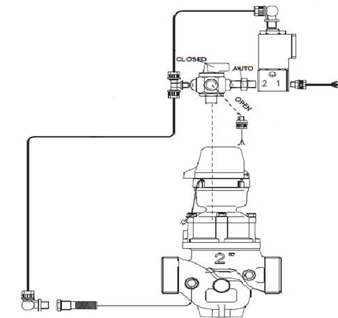
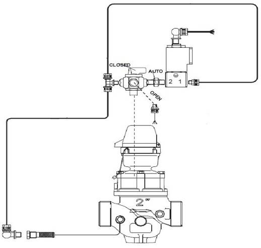
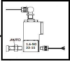
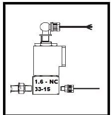
There are two main differences between the NormallyClosed (NC) and NormallyOpen(NO) configurations of the Flow3. In the Normally Closed configuration, the 8mm tube that is venting to the atmosphere is on the side ofthe solenoid, and thesolenoid has the letters “NO” on it. In the Normally Open configuration, the 8mmtube venting to the atmosphereis at the top of the solenoid, and the solenoid has the letters“NC” on it.
A Normally Open solenoid isthe correct part fora Normally Closed valve. A Normally Closed solenoid isthe correct part fora Normally Open valve.
This is a NormallyClosed (NC) Flow3:
This is a NormallyOpen Flow3:
This is a Normally Open solenoid (used for the Normally Closed Flow3):
This is a Normally Closed solenoid (used for the Normally Open Flow3):
HOW TO CONVERT A NORMALLY OPEN FLOW3 TO NORMALLY CLOSED
STEP 1 Loosen the two plasticcompression fittings on the 8mm tubing comingoff the side and top of the solenoid. Gently remove the tubing and the 90° elbow fittings,and set them all aside.You’ll add these to the replacement solenoidin Step 6.
STEP 2 Using an adjustable wrench,get a firm grip on the brass union fitting directly below the solenoidbase with one hand, and unscrew the solenoid and itsbrass base with the other hand. If the solenoid hits the body of the valve, preventingyou from unscrewingit, grab the base of the entire copper assembly that attaches to the main Flow3 valve body and twist it slightly counterclockwise, giving the solenoidroom to turn.
STEP 3 Clean off any excess Teflon tape by buffingthe end of the pipe threads with a wire brush. Applya fresh, singlewrap of Teflontape to the end of each pipe, making sure the hole isn’t obstructed by the tape.Again, scrape away any excess tape if necessary.
Tip: Twist one end of the Teflon tape to make it slim and begin the wrap by anchoring this slim end in the threads.
STEP 4 Look at the replacement solenoid and make sure it has “NO” stamped on the side. On the side of the solenoid, you’ll see a small metal lever called the plunger bypass lever, which only moves to either a 9 o’clockposition perpendicular to thesolenoid or a 12 o’clockposition parallel with the solenoid.Move the lever to the 9o’clock position and install the solenoid so that the lever is pointing in the same direction as the three-way valve.
If you install it with the lever pointingin the opposite direction as the three-way valve, water will shoot out of the end. At the base of the solenoid,you’ll also see the numbers “1” and “2”. Make sure you’ve positioned the solenoid so that “2” isconnected to the brass union of the three-way valve.
STEP 5 Hand-tighten the solenoid by screwing it onto the pipe threading, making it snug but not excessively tightening it. You can gently twist and turn the solenoiditself if it’s butting up against the main Flow3 valve body and register,but don’t remove the solenoidfrom its metal base. There’s a spring inside that you would risklosing.
STEP 6 Once all the assemblies are on snug,we’ll relocate the 90° plasticelbow fittings we removed from the old solenoid to the replacement solenoid. Add a small amount of Teflon tape to the threads on each elbow, making sure the tape is not obstructing the hole, and carefully screw them back onto the side and top of thesolenoid, making sure to avoid cross-threading them.
STEP 7 Take your short pieceof 8mm tubing and push it onto the end of the 90°elbow fitting on the side of the solenoid, slide the black plastic compression nut up, and screw it into place by hand. Be sure to make it snug, but don’t over-tighten to avoid breaking the fittings. The side of the solenoidwill now be venting to theatmosphere, meaning it won’t be attached to anything.
STEP 8 Connectthe 8mm tubing extending from the blue plastic tee fitting onto thesecond 90° elbow at the top of the solenoid.Slide the black plastic compression nut up, and screwit into place by hand.
STEP 9 Turn on the water supply and check for leaks, tightening the fittings if necessary. Rewire the solenoid if there are no leaks. Then test the master valve.
HOW TO CONVERT A NORMALLY CLOSED FLOW3TONORMALLY OPEN
STEP 1 Loosen the two plasticcompression fittings on the 8mm tubing coming off the side and top of the solenoid. Remove the tubing and the 90° elbow fittings, and set them all aside.You’ll add theseto the replacement solenoid in Step 6.
STEP 2 Using an adjustable wrench,get a firm grip on the brassunion fitting directlybelow the solenoid base with one hand, and unscrew the solenoid and base with the other hand. If the solenoid hits the body of the valve, preventing you from unscrewingit, grab the base of the entire copper assembly that attaches to the main valve body and twist it slightlycounterclockwise, giving the solenoid room to turn.
STEP 3 Clean off any excessTeflon tape by buffing the end of the pipe threads with a wire brush. Apply a fresh, single wrap of Teflon tape to the end of the pipe, making
sure the hole isn’t obstructedby the tape. Again, scrape away any excess tape ifnecessary.
Tip: Twist one end of the Teflon tape to make it slim and begin the wrap by anchoring this slim end in the threads.
STEP 4 Look at the replacement solenoid and make sure it has “NC” stamped on the side. On the side of the solenoid, you’llsee a small metal levercalled the plunger bypass lever, which only moves to either a 9 o’clockposition perpendicular to thesolenoid or a 12 o’clockposition parallel with the solenoid.Move the lever to the 9o’clock position and install the solenoid so that the lever is pointing in the same direction as the three-way valve.
If you install it with the lever pointingin the opposite direction as the three-way valve, water will shoot out of the end. At the base of the solenoid,you’ll also see the numbers “1” and “2”. Make sure you’ve positioned the solenoid so that “2” isconnected to the brass union of the three-way valve.
STEP 5 Hand-tighten the solenoid by screwing it onto the pipe threading, making it snug but not excessively tightening it. You can gentlytwist and turn the solenoid itself if it’s buttingup against the main Flow3 valve body and register,but don’t remove the solenoidfrom its metal base. There’s a spring inside that you would risklosing.
STEP 6 Once all the assemblies are on snug, we’ll relocatethe 90° plasticelbow fittings we removed from the old solenoid to the replacement solenoid. Add a small amount of Teflon tape to the threads on each elbow, making sure the tape is not obstructing the hole, and carefully screwthem back onto the side and top of the solenoid, making sure to avoid cross-threading them.
STEP 7 Take your short piece of 8mm tubing and push it onto the end of the 90° elbowfitting at the top of the solenoid,slide the black plastic compression nut up, and screw it into place by hand. Be sure to make it snug, but don’t over-tighten to avoid breakingthe fittings. The top of the solenoidwill now be venting to theatmosphere, meaning it won’t be attached to anything.
STEP 8 Connect the 8mm tubing extendingfrom the blue plastic tee fitting onto the second 90° elbow on the side of the solenoid.Slide the black plastic compression nut up, and screwit into place by hand.
STEP 9 Turn on the water supply and check for leaks, tightening the fittings if necessary. Rewire the solenoid if there are no leaks. Then test the master valve.