
Start Here
Why are we talking two-wire troubleshooting process?
Hydropoint takes pride in having the best two-wire resources online, E-mail or over the phone. This information will enable you to support any customer two-wire issues you may run into. Want a general overview of a two-wire system and two-wire system troubleshooting? See Two-wire System Overview.
- Gain agreement on the customer issue. Customer reported two-wire issues will fall into the following categories:
- One two-wire device is no longer talking to the controller.
- Many two-wire devices are no longer talking to the controller.
- No two-wire devices are talking to the controller.
- Two-wire over current (Current >1.5 amps).
- Check controller messages and map markers, if controller is online. This will help you decide the correct process article to follow with the customer. Check two-wire device description and map markers if available for additional context.Two-wire communication is failing on how many devices?One or two Many All Follow the Resolving a Single Two-Wire No Response Message process. Follow the Resolving Many Two-Wire No Response Messages process.Follow the steps outlined in the Testing the Controller section of the Resolving a Two-Wire Over-Current process.
For two-wire over current troubleshooting, please use the Resolving a Two-Wire Over-Current process.
Two-wire Troubleshooting Decision Tree (Compilation of articles linked in above decision tree.)
What is the two-wire issue type?
Over-Current Message
Single Device "No Reply," "No Response," or "Two-wire communication failure"
Multiple Devices with "No Reply," "No Response," or "Two-wire communication failure" across a large section
Communication failure on all devices
An over-current message occurs when current drawn by the two-wire exceeds the 1.5 amp threshold. This can be caused by overloading the circuit, a circuit short, ground fault, or arc fault.
Tools Required
Multimeter
#2 Phillips screwdriver
Step 1: Test the controller
- Disconnect power from the controller
- While powered down, disconnect the two-wire going to the field (and common wire if using conventional with two-wire combo)
- Power up the controller
- Verify approximately 34VAC on the two-wire terminals
- Legacy 3200 Only: If no voltage, check if two-wire status is OFF. Navigate to Advanced → two-wire settings → set "two-wire always on" to YES
- Go to Self Test and select "check two-wire addresses" or “test all two-wire devices”
No over current message
Over current message persists
Problem is on the wire path. Verify the customer has the appropriate tools for troubleshooting.
Tools Required
An approved mA clamp meter (Armada Pro 95i or Tempo 360B). The correct meter for troubleshooting should have microamp resolution, measure true RMS and have a Low Pass Filter feature.
#2 Phillips screwdriver
Wire stripper
AC solenoid
I have the tools to troubleshoot
I do NOT have a milliamp clamp meter
Process - Finding a short with a mA clamp meter:
- Isolate the over-current to a single two-wire path (if multiple exist at the controller)
- Disconnect any loops in the two-wire path
- Wire an AC solenoid between the red wire and the red terminal at the controller
- Set the clamp meter to measure AC Amps
- Clamp around the RED wire and record the mA measurement
- Follow the mA measurement from the controller outwards, taking readings in every valve box, or use binary search methodology
- Clamp every red wire at every wire connection until you reach a device that measures a large majority of the mA measured at the controller.
What you'll find:
Following the mA value will lead you to:
- A faulty device
- A broken wire
- A compromised connection (either in a valve box or buried)
Action: Replace the faulty device, repair broken wire, or replace compromised connection.
Proper Splicing Procedure:
- Use NEW DBR/Y-6 connectors (included with every decoder set)
- Ensure wires are not loose in the wire nut
- Push the wire nut to the rounded base of the grease cap
- Before closing the valve box, ensure rounded base of grease caps point UP
Process - Split Half Method:
- Isolate the over-current to a single two-wire path (if multiple exist)
- Begin halving that two-wire path and connecting each half to the controller
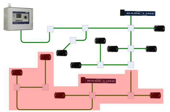
- Check the controller for an over-current message
- Message goes away → Problem is in the disconnected half
- Message persists → Problem is in the connected half
- Reconnect the other half, find the midpoint of the section containing the problem, and disconnect it
- Check the controller for the over-current message again
- Continue this binary search process until you find the trouble device or wire section
Action: Replace the faulty device or repair the problematic wire section.
Proper Splicing Procedure:
- Use NEW DBR/Y-6 connectors (included with every decoder set)
- Ensure wires are not loose in the wire nut
- Push the wire nut to the rounded base of the grease cap
- Before closing the valve box, ensure rounded base of grease caps point UP
Contact HydroPoint Support (support@baselinesystems.com or 866-294-5847)
Use this section when you have an isolated two-wire device communication failure affecting only one device.
Step 1: Verify the Message Details
Check that the message lists a specific device ID. Messages showing "No reply," "No response," or "Two-wire communication failure" indicate a two-wire communication problem. When possible, check for controller map markers. They will help you visualize the site and problem. If none exist, suggest creating them. The geolocate tool in Mobile Access is a great way to do so.
Step 2: Check Two-Wire Addresses
- Turn the dial to Self Test and run a check of two-wire addresses (This eliminates device address issues)
- BaseStation 1000 or SubStation: Run a device search (address check is built-in)
- Re-test the two-wire device after checking addresses
Communication still fails - Continue troubleshooting
Step 3: Test the Device at the Controller
Required Tools:
- #2 Phillips screwdriver
- Wire stripper
Process:
- Pull the two-wire device from the wire path and valve box
- Bring device to controller
- Disconnect all other two-wire from controller
- Connect only the suspect device and perform a device test from the BaseStation test menu
Communication failure - Device is faulty
Test returns okay status (or open circuit solenoid)
Action: Replace the two-wire device.
Contact HydroPoint Support if you need assistance: support@baselinesystems.com or 866-294-5847
Re-splice into Field Location
The issue is likely problematic splices due to corrosion from water intrusion.
Required Tools:
- NEW 3M DBR/Y-6 connectors in waterproof capsule (These CANNOT be reused)
- Wire stripper
- #2 Phillips screwdriver
Proper Splicing Procedure:
- Use NEW DBR/Y-6 connectors (included with every decoder set)
- Ensure wires are not loose in the wire nut
- Push the wire nut to the rounded base of the grease cap
- Before closing the valve box, ensure rounded base of grease caps point UP
Use this section when multiple devices show communication failures across a large section of two-wire.
Required Tools - CRITICAL
- #2 Phillips screwdriver
- Wire stripper
- Approved mA clamp meter such as: Armada Pro 95i or Tempo 360B
Why these specific meters? Not all mA clamp meters have the required resolution. Approved meters have:
- Low pass filter settings for stable mA reading during two-wire communication
- Microamp resolution
- True RMS measurement
Step 1: Check the Controller
- Disconnect the two-wire path from the controller then power cycle the controller.
- Verify there is voltage on the two-wire terminals. Approximately 34VAC.
Legacy 3200 Only: If there is no voltage measured on the two-wire terminals, check if the two-wire status is OFF. If OFF, navigate to Advanced via the dial, then to the two-wire settings menu. Two-wire always on should be set to YES.
Next step
Step 2: Prepare the Wire Path
Before starting:
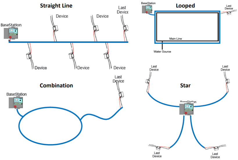
- Identify the wire path configuration
- If it is a looped wire path, break any looped points on the wire path
Next step
Step 3: Calculate Expected mA Draw
Determine the number of devices:
- Collect the controller program summary via USB export (locally) or AdminManager (remotely)
- Sum the mA draw of each two-wire device downstream of your measurement location
Note: The program summary does not include unassigned two-wire devices. All devices on the two-wire path must be assigned for proper expected mA calculation.
Use the Two-wire Device mA Draw Calculator or use below table and do the math (Two-wire device mA draw)(device quantity) = Expected mA draw
Device mA Draw Reference Table:
| Two-wire Device | mA Draw (Controller Two-wire Terminals) |
|---|---|
| BL-5201/01MV/02/04 Station BiCoder | 0.6 |
| BL-5201DC/01-MV DC Station BiCoder | 2.1 |
| BL-5201PR Pump Start BiCoder | 1.1 |
| BL-5303 Air Temperature Sensor | 5.5 |
| BL-5308/09 Flow BiCoder | 9.5 |
| BL-5311/15 Moisture Sensor | 2.6 |
| BL-5401 Coach's Button | 2.8 |
| BL-5402 Event Switch BiCoder | 1.8 |
| BL-5406-KIT Pressure Sensor and BiCoder Combo | 12.2 @ 0 psi / 28.8 @ 150 psi |
| BL-5407-KIT Precipitation Sensor and BiCoder Combo | 9.5 |
| BL-LA01 Lightning/Surge Arrestor | 0.04 |
| BL-PFS Plastic Flow Sensor | 5.7 |
Next step
Step 4: Measure and Compare Current
Measurement Procedure:
- Confirm mA draw on red and black wires match
- With your milliamp clamp meter, clamp the red wire and record the mA value
- Do the same for the black wire
Important: When measuring mA, keep the wire in the center of the clamp meter (alignment markers may be present) and perpendicular to the meter.
Note: Measure when system is idle. mA draw while watering will be higher due to running solenoids.
Next step
Step 5: Locate the Problem
Troubleshooting Method:
Work from the controller down the wire path, or use the binary search method, using the clamp meter to determine where the problem is.
Note: As you work down the two-wire, the expected mA draw changes as the current measured is for downstream devices only.
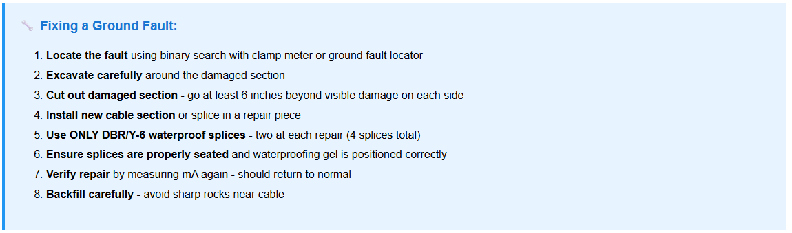
mA on BOTH wires is HIGHER than expected
mA on BOTH wires is LOWER than expected
mA HIGHER or LOWER on ONE wire only
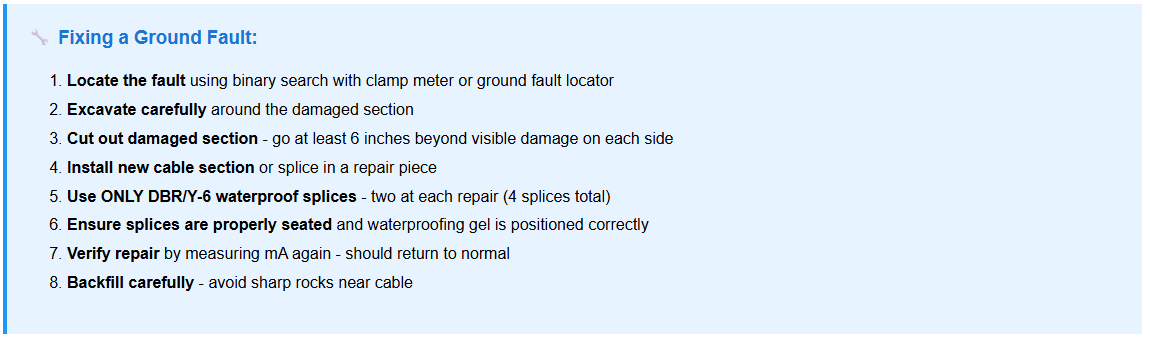
Cause: Problem is a two-wire device pulling too much current or a ground fault.
Location: Where the high mA value drops from a higher than expected number to the expected mA value.
Action: Replace two-wire devices pulling higher than expected current (greater than 30% over average). Repair any found ground faults.
Proper Splicing Procedure:
- Use NEW DBR/Y-6 connectors (included with every decoder set)
- Ensure wires are not loose in the wire nut
- Push the wire nut to the rounded base of the grease cap
- Before closing the valve box, ensure rounded base of grease caps point UP
Cause: Disconnection at one or more locations on the wire path.
Location: Where the expected mA value drops from expected value to near or to zero. Use Device mA Draw table to see how many two-wire devices can be summed to match your mA measurement. This gives you a starting location to inspect your wire path.
Action: Replace connections at the last reading of expected mA. Two-wire devices measuring lower than expected current can be recovered if you can cut back to clean wire. If corrosion is found too close to the two-wire device, it should be replaced.
Proper Splicing Procedure:
- Use NEW DBR/Y-6 connectors (included with every decoder set)
- Ensure wires are not loose in the wire nut
- Push the wire nut to the rounded base of the grease cap
- Before closing the valve box, ensure rounded base of grease caps point UP
The other wire reads the expected value.
Higher than expected on one wire:
- Cause: Problem is a two-wire device pulling too much current or a ground fault.
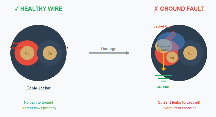
- Action: Replace two-wire devices pulling higher than expected current (greater than 30% over average). Repair any found ground faults.
Lower than expected on one wire:
- Cause: Corroded wire, wire damage, or disconnected two-wire devices (via wire damage or bad splices)
- Action: Repair or replace the affected wire and connections
Proper Splicing Procedure:
- Use NEW DBR/Y-6 connectors (included with every decoder set)
- Ensure wires are not loose in the wire nut
- Push the wire nut to the rounded base of the grease cap
- Before closing the valve box, ensure rounded base of grease caps point UP
Tools Required
Multimeter
Milliamp clamp meter
Step 1: Test the Controller
- Power cycle the controller
- Verify approximately 34VAC on the two-wire terminals
- Legacy 3200 Only: If no voltage, check if two-wire status is OFF. Navigate to Advanced → two-wire settings → set "two-wire always on" to YES
- If the correct voltage can be measured on the two-wire terminals, turn the dial to Self Test and select "check two-wire addresses" or “test all two-wire devices”
I measure no voltage on my two-wire terminals
I have voltage but all my devices are still in error
Contact HydroPoint Support (support@baselinesystems.com or 866-294-5847)
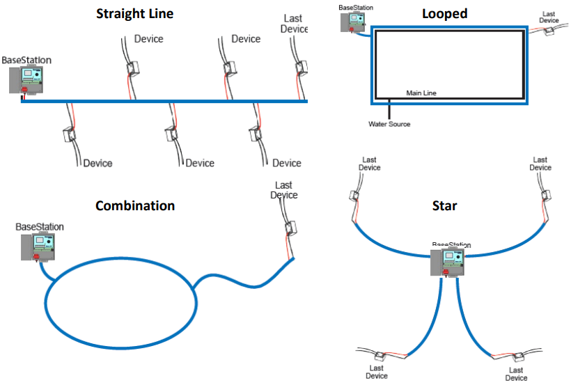
Step 1: Prepare the Wire Path
Before starting:
- Identify the wire path configuration
- If it is a looped wire path, break any looped points on the wire path
Next step
Step 2: Calculate Expected mA Draw
Determine the number of devices:
- Collect the controller program summary via USB export (locally) or AdminManager (remotely)
- Sum the mA draw of each two-wire device downstream of your measurement location
Note: The program summary does not include unassigned two-wire devices. All devices on the two-wire path must be assigned for proper expected mA calculation.
Device mA Draw Reference Table:
| Two-wire Device | mA Draw (Controller Two-wire Terminals) |
|---|---|
| BL-5201/01MV/02/04 Station BiCoder | 0.6 |
| BL-5201DC/01-MV DC Station BiCoder | 2.1 |
| BL-5201PR Pump Start BiCoder | 1.1 |
| BL-5303 Air Temperature Sensor | 5.5 |
| BL-5308/09 Flow BiCoder | 9.5 |
| BL-5311/15 Moisture Sensor | 2.6 |
| BL-5401 Coach's Button | 2.8 |
| BL-5402 Event Switch BiCoder | 1.8 |
| BL-5406-KIT Pressure Sensor and BiCoder Combo | 12.2 @ 0 psi / 28.8 @ 150 psi |
| BL-5407-KIT Precipitation Sensor and BiCoder Combo | 9.5 |
| BL-LA01 Lightning/Surge Arrestor | 0.04 |
| BL-PFS Plastic Flow Sensor | 5.7 |
Next step
Step 3: Measure and Compare Current
Measurement Procedure:
- Confirm mA draw on red and black wires match
- With your milliamp clamp meter, clamp the red wire and record the mA value
- Do the same for the black wire
Important: When measuring mA, keep the wire in the center of the clamp meter (alignment markers may be present) and perpendicular to the meter.
Note: Measure when system is idle. mA draw while watering will be higher due to running solenoids.
Next step
Step 4: Locate the Problem
Troubleshooting Method:
Work from the controller down the wire path, or use the binary search method, using the clamp meter to determine where the problem is.
Note: As you work down the two-wire, the expected mA draw changes as the current measured is for downstream devices only.
mA on BOTH wires is HIGHER than expected
mA on BOTH wires is LOWER than expected
mA HIGHER or LOWER on ONE wire only
Cause: Problem is almost always in a valve box (two-wire device)
Location: Where the high mA value drops to the expected mA value
Action: Replace two-wire devices pulling higher than expected current (greater than 30% over average)
Proper Splicing Procedure:
- Use NEW DBR/Y-6 connectors (included with every decoder set)
- Ensure wires are not loose in the wire nut
- Push the wire nut to the rounded base of the grease cap
- Before closing the valve box, ensure rounded base of grease caps point UP
Cause: Disconnection at one or more locations on the wire path
Location: Where the expected mA value drops from expected value to near zero or zero.
Action: Replace connections at the last reading of expected mA. Two-wire devices measuring lower than expected current can be recovered if you can cut back to clean wire. If corrosion is found too close to the two-wire device, it should be replaced.
Proper Splicing Procedure:
- Use NEW DBR/Y-6 connectors (included with every decoder set)
- Ensure wires are not loose in the wire nut
- Push the wire nut to the rounded base of the grease cap
- Before closing the valve box, ensure rounded base of grease caps point UP
The other wire reads the expected value.
Higher than expected on one wire:
- Cause: Leak to ground on that wire
- Action: Repair or replace the affected wire and connections
Lower than expected on one wire:
- Cause: Corroded wire, wire damage, or disconnected two-wire devices (via wire damage or bad splices)
- Action: Repair or replace the affected wire and connections
Proper Splicing Procedure:
- Use NEW DBR/Y-6 connectors (included with every decoder set)
- Ensure wires are not loose in the wire nut
- Push the wire nut to the rounded base of the grease cap
- Before closing the valve box, ensure rounded base of grease caps point UP