
Step 1: Isolate the Issue
Before digging into the field wiring, determine whether the problem is:
- A 2W path (field wiring/decoders) issue, or
- A failing chassis.
Start at the controller:
Turn off the 2w path on the chassis and see if mA readings drop
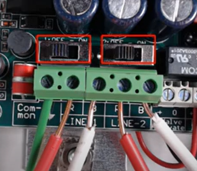
Disconnect the 2w path from the controller and clear alerts on the controller to see if short alerts repopulate. If short alerts repopulate with no 2w path connected, you know that the issue is with the PBT chassis.
RMA the chassis if it is under warranty
Key Indicators at the Controller
- A “Line Out” LED often indicates a problem on the 2W path.
- An alarm or alert will usually be present when a fault exists.
Safety Note:
There is always voltage present on a 2W path. Use caution at all times when handling wires and measuring current.
Step 2: Use Milliamp (mA) Readings to Assess Path Health
Milliamp readings provide valuable insight into the overall health of the 2W path.
- Each decoder draws approximately 0.5 mA.
- The controller itself contributes about 1–3 mA.
By knowing how many decoders are on the system, you can calculate an expected total mA draw and compare it to your actual reading.
Step 3: Activate the Short-Finding Tool
To activate the short-finding tool at the controller following the steps below:
- Press the Left Arrow once
- Press Enter on “Tests”
- Press the Down Arrow once until “Short Finding” appears
- Press Enter to enable Short-Finding Mode
When activated, the controller sends a diagnostic signal down the 2W path that can be detected using a milliamp clamp meter.
Step 4: Measure Current and Track the Short
Tools Required
- Site map of the 2W wire path
- Milliamp clamp meter (Armada Pro93 recommended)
At the Controller
- Use a milliamp clamp meter to measure current on the 2W path at the controller.
- Record this baseline reading.
In the Field (Valve Boxes)
Move methodically along the wire path using a site map.
At each valve box:
- Take four measurements total:
- Each wire coming into the box
- Each wire leaving the box
How to Interpret Readings
- The mA reading should decrease slightly as you move down the path.
- High mA reading → the wire section is before the short.
- Low mA reading → the wire section is after the short.
By comparing incoming vs. outgoing readings at each valve box, you can pinpoint the exact section of wire where the fault exists.
Step 5: Narrow Down and Repair
Once the problem section is identified:
- Inspect for common issues such as:
- Damaged insulation
- Nicked wires
- Water intrusion
- Poor splices
- Repair or replace the damaged section.
- Re-test the system to confirm alerts clear and mA readings return to expected levels.