
Appendix M – Event Logs
Log files are useful in determining what happened in the past to help troubleshoot and clarify behavior that is not understood. There are several log files that can be enabled in the system:
Event File
The event file is a monthly file that is created in the Archive folder for the month. Its file name is “Evnt_yyyyMM.csv.” This file is always active and cannot be suppressed. For the current month, the file is not compressed and can grow quite large. When the file reaches 5 Mbytes, the oldest 0.5 Mbytes of records of the file and erased and additional new records are appended to the end of the file. This keeps the file from growing without bounds. At the beginning of a new month, the previous month’s event file is compressed, and the file name now becomes “Evnt_yyyyMM.zip”. The compression code makes the zip file in the \temp\ folder, which is in RAM (faster zipping) and then copies it to the archive folder in flash.
Event lines are kept in a buffer and then a group of lines are written to the event file at one time. The following conditions will cause the buffer to be written to flash:
- At the top of every minute
- When the firmware is being updated, just before the reboot.
- If the user requests a reboot or halt
- If the system has a recoverable crash.
- If the system has an unrecoverable crash, it will attempt this before stopping.
Event Line Format: each line has a fixed portion that is always the same and each field is separated with a comma. After the fixed portion there are one or more variable fields that use a key-value format:
- Fixed
- Date and time = “MM/dd/yyyy HH:mm:ss”
- Other fields as needed.
- Key=Value data
Category |
SubCategory |
Who or Actor |
|
AL = Alarm AN = Pressure Decoder BM = BaseManager CP = Control Point ET = Evapotranspiration FM = Flow Meter FS = FlowStation IO = IOT Server ML = Mainline MS = Moisture Sensor MV = Master Valve NM = Cloud Network Module NT = Ethernet PG = Program PM = Pump PS = Pump Station RG = Rain Gauge Decoder SS = SubStation SW = Event Switch SY = System TS = Temperature Sensor TW = Two Wire WS = Water Source ZP = Primary Zone ZN = Zone |
AD = ET Adjustment BK = Backup BT = Boot up CA = Clear All CB = Calibration CC = Configuration Change CE = Configuration Error CL = Clear CN = Connect DC = Disconnect DN = Done DR = Drop DS = Disable DT = Date/Time ER = Error FV = Flow Variance HF = High Flow HR = Hourly Data LF = Learn Flow LP = Low Pressure LR = Learn Flow Results MR = Manual Run OF = Off PA = Pause RD = Reading RS = Restore RN = Run RL = Run List RX = Receive SB = Subtract SE = Set SK = Skipped SO = Soak SR = Start ST = Status SP = Stop TF = Traffic TT = Transmit TX = Text UD = Update VT = Variance Test WA = Wait WT = Water |
AD = Administrator BL = Baseline Commander BM = BaseManager CM = Cloud Network Module CP = Control Point DL = Dial DT = Date/Time ED = Event Date ET = Ethernet FJ = Flow Jumper FM = Flow Meter FS = FlowStation IO = IOT Server ML = Mainline MS = Moisture Sensor MV = Master Valve NT = Network OP = Operator PG = Program PJ = Pause Jumper PP = Program Priority PR = Programmer PS = Pressure Sensor PZ = Primary Zone RA = Rain Shutdown RG = Rain Gauge RJ = Rain Jumper SB = SubStation SW = Event Switch SY = System TE = Test Engine TS = Temperature Sensor US = User WS = Weather Station WW = Water Window ZN = Zone |
Examples of some event lines:
Network Traffic Metering
this logs network traffic and posts values every hour.
(Date Time, System, Traffic, Network, Type, Bytes In, Bytes Out, Packets In, Packets Out)

- Ethernet: type is “ET”
- Cloud Network Module: type is “NM”
- Ethernet: type is “CE”
- WiFi: type is “CW”
- Cell: type is “CC”
- BaseManager/AppManager: type is “BM.”
- FlowStation: type is “FS”
- SubStations (one line for each one): type is “SS-01.”
- IOT server: type is “IOT.”
Substation Connection
- NU = number
- SN = serial number
- MC = MAC address
- TY = type {SS, RV, or CP}
- VR = firmware version
- HW = hardware version
- TX = text of network path

Disconnect Entries
For FlowStation & Substations

- The network path has been appended and the best reason for the disconnect, in this case there was not a reply to a Ping command sent to the SubStation.
- The options for the Network Path are:
- Ethernet
- CN_Ethernet
- CN_WiFi
- CN_Cell
- The IOT field is only added for connections that use the IOT server.
- Possible reasons for a disconnect are:
- IOT Offline
- Socket Closed
- No Ping Reply
Flow Variance
Flow Variance strikes, zones, and mainlines

- ML = mainline number
- ZN = zone or list of zones separated by a semi-colon
- LX = low variance enabled (otherwise, high variance)
- SJ = strikes detected (not shutdown)
- SK = strikes towards shutdown
- TH = variance threshold (percent)
- AC = actual flow reading (gpm)
- EX = expected flow value (gpm)
FlowStation Managed Mainline

- ML = mainline number
- FS = FlowStation variance status (HI, LO, or OK) – reported by FlowStation for the mainline group that includes this mainline on these 3200 controllers
- ZN = zone or list of zones separated by a semi-colon
- LX = low variance enabled (otherwise, high variance)
- SJ = strikes detected (not shutdown)
- SK = strikes towards shutdown
- TH = variance threshold (percent)
- AC = actual flow reading (gpm)
- EX = expected flow value (gpm)
PumpStation Status
PumpStation hourly status/data event line

- IP = address of PumpStation
- PR = pressure (psi)
- SS = Drive status
- PD = PID feedback
- FQ = output frequency
- AM = output current
- TM = total run time
- ER = fault type [total IO count / missed IO count]
RainGauge line:
Hourly Log & Test Results

- RG = rain gauge number
- SN = decoder serial number
- VT = two-wire voltage drop
- VK = accumulated, total rain fall
- VI = hourly rainfall
- VH = current rainfall rate
Run Time Results:
Enable with dynamic logging control [PENDING]
- Program elapsed run time to completion vs. estimated.
- Program paused time.
- Program elapsed time was increased by water window.
- FlowStation mainline wait time before getting water.
- FlowStation mainline received a fraction of the water that was requested.
- Flow meter flow and usage
- Zone or zone group flow rate
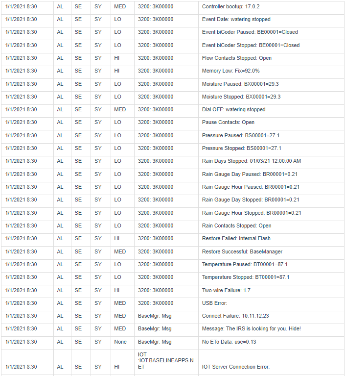
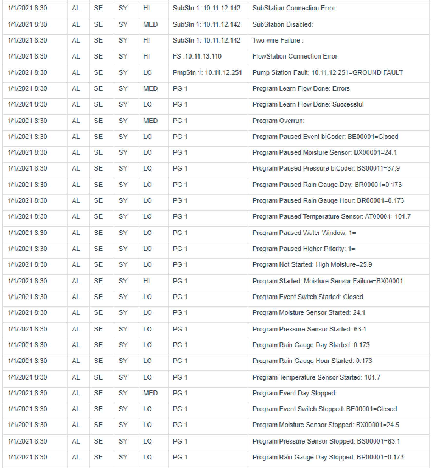
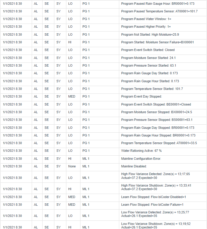
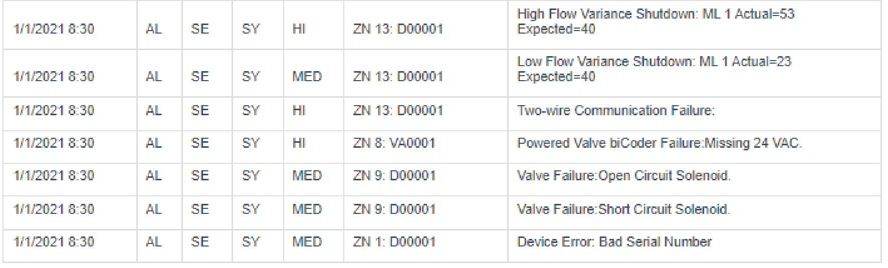
Event log entries for Alarms:
Configuration Errors
- Zones not assigned to a mainline.
- Zones not in a program.
- Zones with a zero design-flow value.
- If local mainline is using manage by flow.
- Local water source that is enabled and not assigned to a local control point.
- Local control point that is enabled and not assigned to a local mainline.
- Control point with a flow meter that has a zero design-flow.
- Control point with shutdown conditions that does not have a flow meter.
- Control point with shutdown conditions that does not have a pressure sensor.
- Local mainline that is enabled and has no zones.
- Local mainline that is enabled and manage by flow and does not have a design flow.
- Sensor devices that are not used.
- Event switch = not start/pause/stop condition, no empty condition.
- Flow meter = not control point.
- Moisture sensor = not start/pause/stop condition, no empty condition.
- Pressure sensor = not start/pause/stop condition, no empty condition.
- Rain Gauge = not start/pause/stop condition.
- Temperature sensor = not start/pause/stop condition.
- Sensor devices that have bad setup values:
- Flow meter = K-value is zero.
- Pressure sensor = 4mA value is the same as the 20mA value, or the 20mA value is zero.
- Rain Gauge = R-value is zero.
- Valve decoders that are not used: no control point nor booster assignment.
- Master Valve.