
Installation Instructions
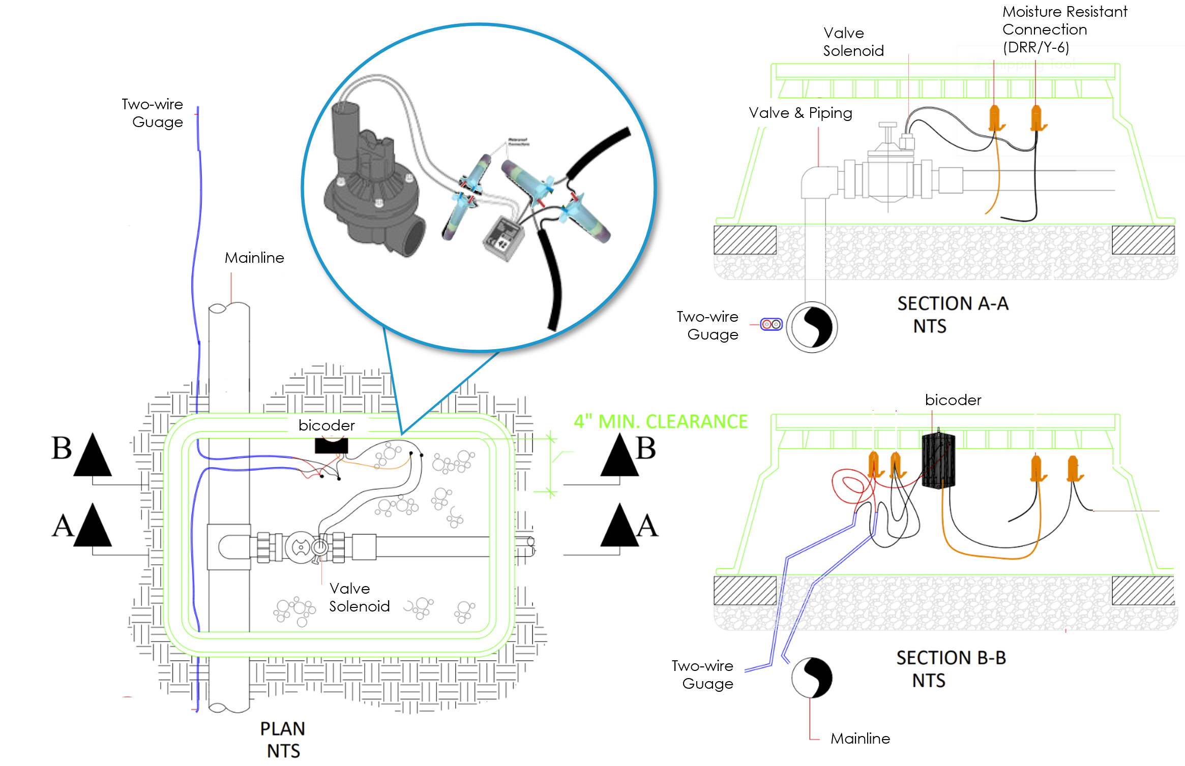
1. Power off the two-wire when installing devices. Leave 24 to 36 inches of slack on the two-wire to allow for easy installation and maintenance.
2. Place the biCoder in the valve box for convenience and protection. Valves can be located a maximum of 150ft from the biCoder location by using additional 14 gauge wires.
BL-5201/5202/5204 biCoder™ Wiring Diagram
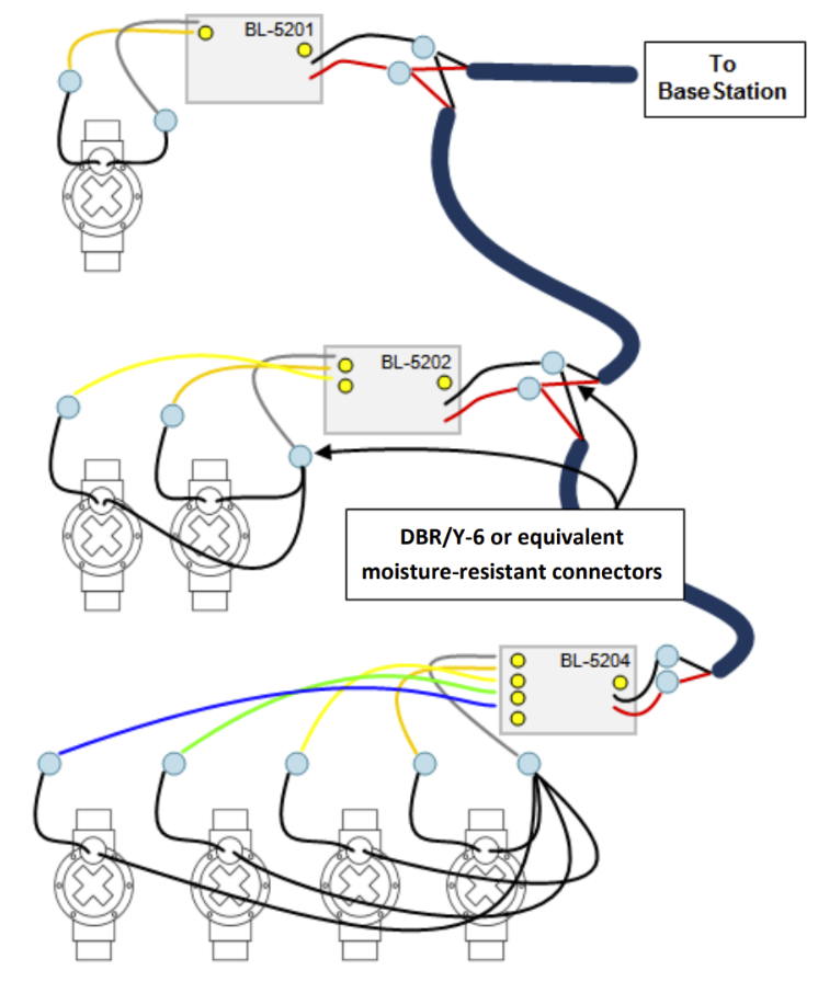
3. Wire the valves according to the wiring diagram label on the back of each biCoder. All connections must use 3M9tm) DBR/Y-6 or equivalent moisture-resistant connectors. The biCoder wires must not have electrical contact with soil or water!
Principle Wiring Techniques
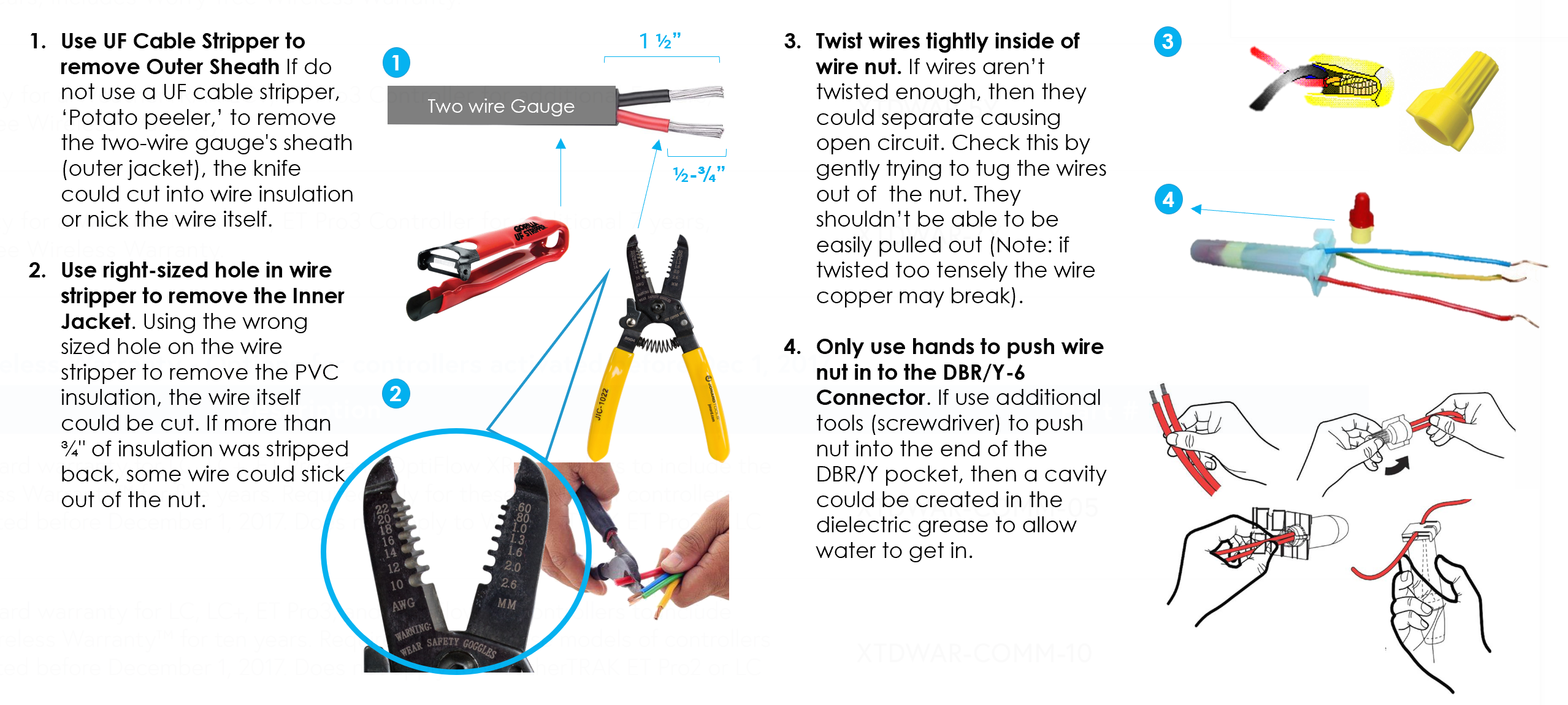
4. Connect the red and black wire from the biCoder to the corresponding red and black wires on the two-wire using 3M™ DBR/Y-6 or equivalent connectors. It is critical that polarity be maintained.
5. Using the controller, test the connections and assign the biCoder addresses as instructed in the controller’s user manual.
Note
The common wires cannot be shared between different biCoders.
References
- BL_BL-5201-2-4_Valve_biCoder_Install_Guide.pdf (1, 2, 4 Station biCoders respectively)
- BL_BL-5201PR_Pump_Start_biCoder_Install_Guide.pdf (pump start relay switching biCoder)
- BL_BL-5406_Pressure_biCoder_Kit_Install_Guide.pdf (4 - 20 mA biCoder and pressure sensor)
- BL_Precip Sensor_BL5407_Install Manual.pdf