
This internal knowledge base article is the central reference for Admin Tool configuration and flow monitor setup, covering the end-to-end tasks required to create and manage accounts, sites, and monitoring points, as well as configure and validate FM250, FM300, and FM350 devices. Content is organized by task and device type using expandable sections to make information easy to find, and includes internal-only procedures with links to relevant customer-facing articles where applicable.User & Site Management
Create a new account
Accordion Body
Create a new site
Accordion Body
Assign users to a site
Accordion Body
Device Setup
FM250 Single
FM250 Compound
Section 01
Who this is for & when to use it
This article is for the Project Support Specialist (PSS) team. It walks through manually configuring a Low Flow FM250 and linking it to a High Flow FM250 to form a compound water meter in the Admin Tool.
PRIMARY PATH — THE INSTALLER APP
Most compound meters are set up in the field with the WC Installer App; that configuration and setup process is documented in the FM250 Installation Guide. This article covers the Admin Tool process — manual setup when the Installer App wasn't or couldn't complete the install, plus verification, device replacement, and the hand-off to CSM.
Configuring a new FM250 in the Admin Tool itself does not change. What is new is the option to link two FM250 devices to a shared Monitoring Point (Water Meter), which forms the compound meter solution. Use this manual process whenever the WC Installer App was not used to complete the compound install — for example:
The technician installed the FM250s without using (or before having) the Installer App.
A device was swapped or re-provisioned and the pairing was lost.
Only one register was set up so far (a phased / partial install).
The installer completed the install as a single device — escalate via the existing Engineering escalation path; do not attempt the manual fix (see Section 06).
Note
The result is identical to an Installer-App install: two FM250 devices sharing one Monitoring Point, one Low Flow and one High Flow, presented to the customer as a single compound water meter. The WC dashboard shows the combined low-flow + high-flow value as a single number, exactly as the legacy FM200 compound solution does today.
Section 02
How the FM250 compound solution works
A compound water meter has two measuring elements in one service: a positive-displacement (PD) element for low flow and a turbine element for high flow. Total consumption is always the sum of the low-flow register plus the high-flow register. Compound meters sit on high-value commercial accounts (hospitals, universities, manufacturing), and the legacy FM200 dual-sensor device that historically monitored them is being deprecated. The replacement is two FM250 single-magnetometer devices — one per register — combined in the cloud.
The setup is the same whether the meter is an inline compound (both elements in one body with an internal changeover valve) or a bypass compound (a large mainline meter with a parallel bypass loop carrying a smaller low-flow meter). In both cases: one FM250 on the low-flow element, one on the high-flow element, both linked to one Monitoring Point.
WHAT LINKING DOES
The FM250 compound solution uploads hourly and manages alerts in the cloud (not at the edge / device level like the FM200). When two FM250s are linked — manually or via the Installer App — their connection period and reporting time automatically sync. This sync takes effect on thenext daily upload; from then on the two devices report hourly, within 60 seconds of each other.Immediately after linking, the two devices' Reporting Time / Connection Period may not yet match — that is expected, not a failure. The Is Compound behaviour is set automatically by the linking process — there is no manual checkbox to tick.
SET EXPECTATIONS
Because devices communicate hourly, worst-case leak detection latency is roughly 62 minutes (up to a ~60-minute comm cycle plus ~2-minute notification); the average is ~32 minutes. This is expected behaviour, not a fault — tell customers during onboarding, especially on large high-flow services.
SECTION 03
Key concepts
1 · Shared Monitoring Point = the compound meter
The compound meter is the logical entity created when both FM250s reference the same Monitoring Point (Water Meter). The Monitoring Point is what the customer sees.
2 · Low Flow is configured first
You fully configure the LOW FLOW device (Account, Site, Monitoring Point, low-flow register details, calibration) and Save it first. You then use Link Device to attach the HIGH FLOW device, and finally complete the high-flow register details.
3 · Naming convention for the Monitoring Point
Name the Monitoring Point using the Monitor Type and the SN of the low-flow meter register — for example, Domestic (SN:<low-flow register SN>). The low-flow and high-flow registers will often have different meter serial numbers; that is expected.
4 · Independent calibration, combined consumption
Each FM250 keeps its own K Value and Gallons-per-Pulse. Only the resulting consumption is summed in the cloud and shown as a single value.
SECTION 04
Before you begin
- Both FM250 devices are physically installed — one on the low-flow element, one on the high-flow element — and each is communicating.
- You have both Serial Numbers (format
FMS0000002157) and know which device is on which register. - You know the correct Account and Site.
- You have the Monitoring Point details for each register (meter make / model / SN, unit of measure, usage group, location), the install date, and calibration values for each device.
- You have decided the Monitoring Point name per the convention (Monitor Type + low-flow register SN).
- You have Admin Tool access with permission to Edit Water Meters / Device Details.
IMPORTANT — BEFORE YOU UNLINK
Unlinking a device clears its device-details record, and the device must be set up again from scratch — only unlink if absolutely necessary. Calibration follows the Monitoring Point (water meter), not the device: if you unlink a device and move it to a new meter, its calibration stays with the original meter, and the moved device must be recalibrated.
NEED HELP / ESCALATION
If the workflow fails, behaves unexpectedly, or you are unsure how to proceed, escalate to Product Management.
SECTION 05
Manual setup — step by step
The work is in three parts: A. configure and save the Low Flow device, B. link it to the High Flow device, and C. complete the High Flow device's details.
PART A — CONFIGURE THE LOW FLOW DEVICE1
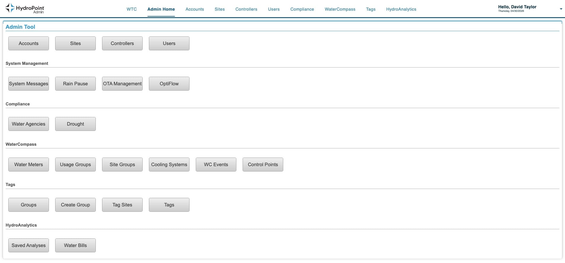
Log in to the Admin Tool and open the Water Meter List
Go to WaterCompass → Water Meters.
2
Find the Low Flow device and click Edit
Set Show filter row to Yes, filter by Serial Number for the device installed on theLOW FLOW register, then click Edit in the Links column. A new, unconfigured device shows empty Monitoring Point fields and the banner “Assign this device to a water meter before linking.”

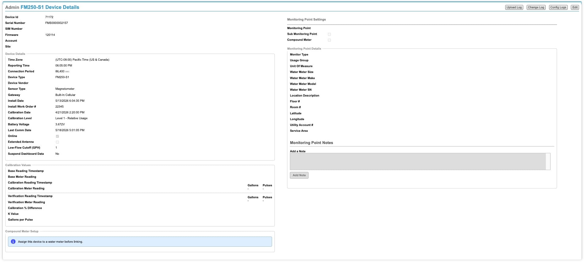
FMS0000002157). Empty Monitoring Point; Compound Meter Setup banner: “Assign this device to a water meter before linking.”3
Fill in Account and Site
Set the Account and Site for the meter. If the Account or Site does not exist yet, you can create it from the Device Details page.
4
Assign a Monitoring Point
Assign the Monitoring Point — create a new one from the Device Details page if needed. Name it per the convention: Monitor Type + low-flow register SN (e.g. Domestic (SN:54321)). This Monitoring Point becomes the shared compound meter the customer sees.
ABOUT THE SCREENSHOTS
The screenshots in this article use test / lab data, so the Monitoring Point names shown (e.g. Carwash (SN:12345)) are sample values and may not follow the convention. The naming convention above — Monitor Type + low-flow register SN — is authoritative.
5
Fill out the Monitoring Point Details
Complete the Monitoring Point Details using the low-flow device and low-flow register values: Monitor Type, Usage Group, Unit of Measure, Water Meter Size / Make / Model / SN, Location Description, Floor #, Room #, Latitude / Longitude, Service Area.
6
Fill out the Install Date
Enter the Install Date for the low-flow device.
7
Fill out the Low Flow Calibration Values
Enter the calibration values for the low-flow device into the Calibration Values block so it carries a K Value / Gallons-per-Pulse.
WHERE CALIBRATION VALUES COME FROM
Calibration values are produced during install from the technician's three button-press readings matched to physical meter photos — see the FM250 Installation Guide for the full explanation. Use the values from the install record for this device.
8
Save
Save the record. You should see “The record was saved successfully.” The Monitoring Point now appears, and the Compound Meter Setup section changes to offer a Link Device button.
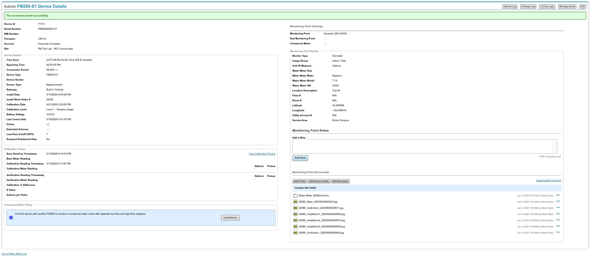
PHASED / PARTIAL INSTALL
If only the low-flow device is installed so far, you can stop here. The saved device operates as a normal single flow monitor until you return and run Part B once the high-flow FM250 is installed and reporting.
PART B — LINK TO THE HIGH FLOW DEVICE9
Click Link Device
In the Compound Meter Setup section, click Link Device to open the “Link Devices for Compound Meter” dialog.
10
Confirm Low Flow, then search and select the High Flow partner
In the dialog, This Device is the device you just saved — confirm its Sensor Position is LOW FLOW. Under Partner Device, search by Serial Number (or Device ID) and select the FM250 installed on the HIGH FLOW register; its Sensor Position is set to High Flow automatically. Confirm the note — both devices will share the same Monitoring Point — then click Link Devices.
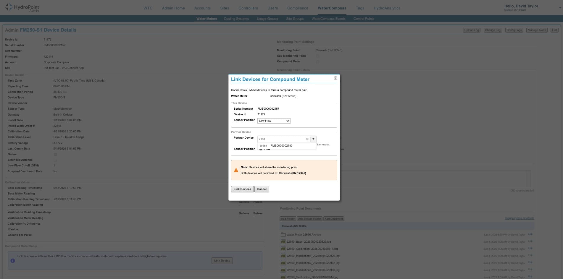
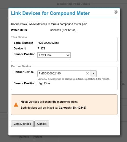
FMS0000002180 = High Flow, both linked to the shared Monitoring Point.CHECK THE PARTNER SN BEFORE YOU CLICK
Double-check the partner Serial Number before clicking Link Devices. Linking the wrong device is only reversible by Unlink, which clears the device record (see Section 04) — so confirm the SN is correct first.
PART C — COMPLETE THE HIGH FLOW DEVICE11
Fill out the High Flow Monitoring Point details
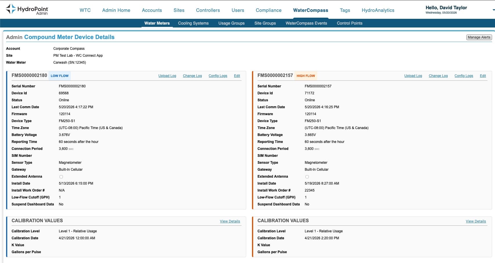
Linking opens the Compound Meter Device Details page with both devices side-by-side. The Low Flow side is populated; the HIGH FLOW side's Monitoring Point details are still empty. Complete the high-flow register's Monitoring Point details (Type, Unit of Measure, Water Meter Size / Make / Model / SN).
12
Fill out the High Flow calibration values
Enter the high-flow device's calibration values (K Value / Gallons-per-Pulse) from its install record — same source as the calibration note in Part A (Step 7). Both devices keep independent calibration.
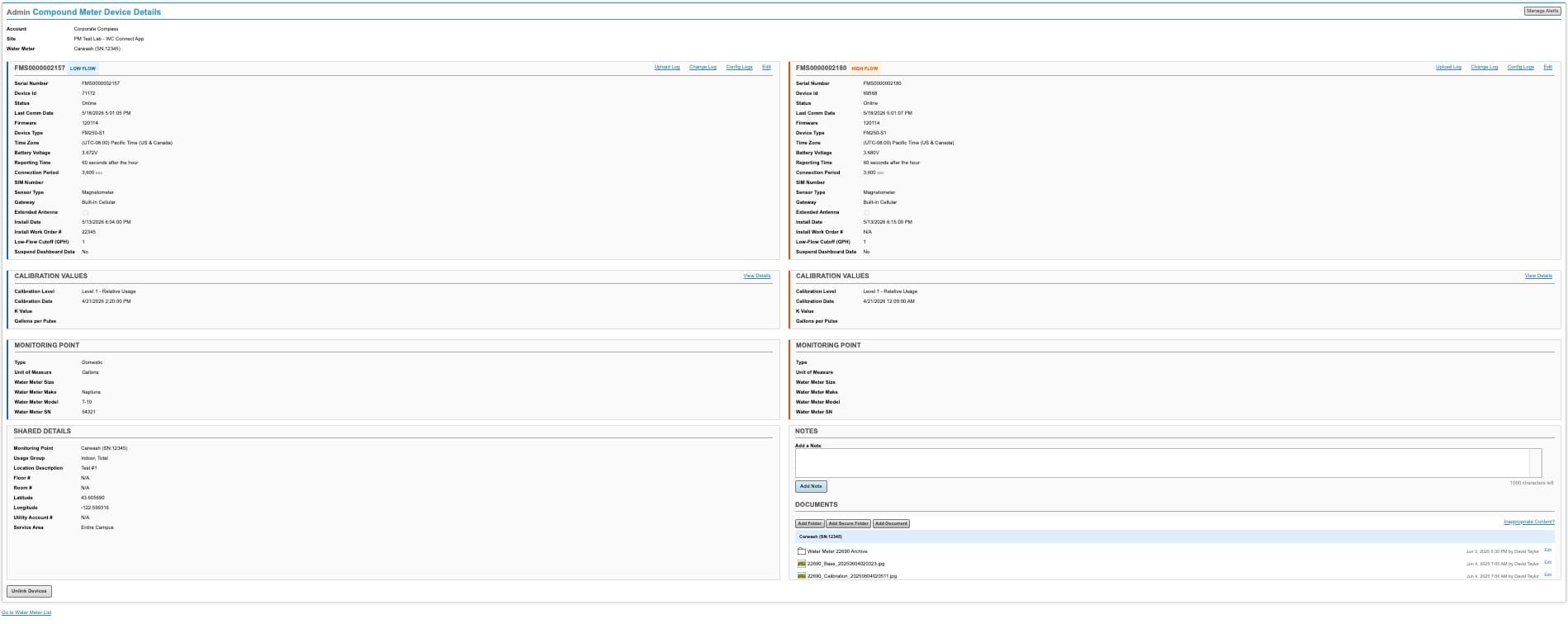
FMS0000002157 Low Flow populated; right FMS0000002180 High Flow Monitoring Point + Calibration still need completing. Shared Details shows the single Monitoring Point. (Reporting Time / Connection Period sync on the next daily upload after linking.)SYNC TIMING — WHAT TO EXPECT
The two devices' Connection Period and Reporting Time sync on the next daily upload after linking; from then on they report hourly, within 60 seconds of each other. If these values do not match immediately after you link, that is normal — do not treat it as a failure or re-do the setup.
DONE-RIGHT TELLS
One LOW FLOW badge and one HIGH FLOW badge (never two of the same); both devices Online; a single shared Monitoring Point in Shared Details; and each device with its own K Value / Gallons-per-Pulse. Reporting Time / Connection Period will match once the next daily upload has run (then both report hourly, within 60 seconds of each other).
SECTION 06
Escalation case: install completed as a single device
Sometimes a field installer uses the WC Installer App but completes the compound meter as a single device — the high-flow FM250 ends up assigned to the Account, Site, and Meter on its own instead of being linked as the high-flow partner.
DO NOT ATTEMPT TO FIX THIS IN THE ADMIN TOOL
Earlier versions of this article described a manual fix — unassign the High Flow device, then run Link Device from the Low Flow side. Do not run that procedure. Unassigning the High Flow device in the Admin Tool will break the calibration readings the installer captured during the install process, and PSS cannot restore them.
What to do instead:
- Escalate via the existing Engineering escalation path. Engineering will combine the two devices server-side so that no installer-captured data or calibration values are lost.
- Do not change the High Flow device's Account, Site, or Meter assignment while the escalation is open.
- Do not Unlink the Low Flow device either — unlinking clears the device record (see Section 04).
WHY ENGINEERING, NOT PSS
The unassign-and-link workflow in the Admin Tool would invalidate the calibration readings the installer captured on the High Flow device during install. Engineering has a server-side path that combines the two devices into a compound pair while preserving the data and calibration values on both sides.
SECTION 07
Replacing devices on a compound meter
Sometimes an FM250 fails or has to be swapped after the original install. The Replace This Device flow swaps an old device for a new one while preserving the Monitoring Point binding, install information, and consumption history. Use it for one device on a compound pair, or for both.
PREREQUISITES
Before you run Replace:
- The new FM250 is physically installed on the same meter register as the device it replaces.
- The new FM250 is online and reporting — it must have communicated at least once so it appears in the Select Device dropdown.
- You have the new device's Serial Number and know which register it sits on.
- You have the new device's calibration values ready from its install record (K Value / Gallons per Pulse) — the new device will need fresh calibration after Replace (see Step 7).
07.1 · Replacing one device (low or high flow)
Use this when only one of the two FM250s on a compound meter is being swapped. The procedure is identical for either the Low Flow or the High Flow device.
1
Log in to the Admin Tool and open the Water Meter List
Go to WaterCompass → Water Meters.
2
Find the OLD device and click Edit
Filter by Serial Number for the device being removed, then click Edit in the Links column.
3
Click Replace This Device
On the Edit Device Details page, click Replace This Device in the top right of the Monitoring Point Settings panel.

4
Verify Water Meter and Current Device
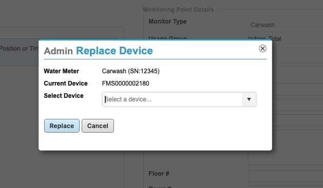
In the Admin Replace Device dialog, confirm the read-only fields before doing anything else:
- Water Meter — should be the customer's compound meter (e.g.
Carwash (SN:12345)). - Current Device — should be the OLD device's SN that you intend to replace.
5
Select the new device's SN
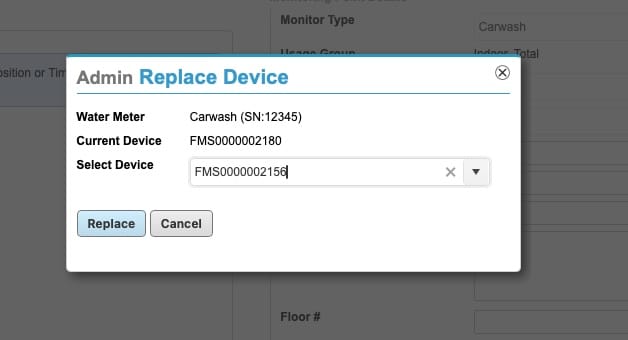
Click Select Device and search for the new FM250's Serial Number. Only devices that are online and reporting will appear in the dropdown.
6
Click Replace
Click the Replace button. The system swaps the old device's details onto the new device record — Monitoring Point binding, Account, Site, install date, Install Work Order #, and all historical consumption data carry over.
7
Calibrate the new device
The new device's K Value and Gallons per Pulse will be blank after Replace — calibration is the only thing not transferred. Enter the new device's calibration values from its install record. See the calibration explainer in Section 05, Step 7 for where these come from (the installer's three button-press readings matched to physical meter photos).
REPLACE PRESERVES DATA — EXCEPT CALIBRATION
Replace transfers device details, install info, and consumption history from the old device to the new one. It does not transfer calibration — each physical sensor has its own K Value / Gallons per Pulse derived from its install readings. The new device must be calibrated after Replace.
Verify before closing the ticket:
- Compound Meter Device Details still shows the correct LOW FLOW + HIGH FLOW pair.
- The new device's Serial Number now appears on the side that was replaced.
- Shared Monitoring Point is unchanged (same Water Meter as before).
- The new device has its own non-blank K Value and Gallons per Pulse.
- Both devices are Online with a recent Last Comm Date.
07.2 · Replacing both devices
If both FM250s on a compound meter must be replaced, do them one at a time, starting with the Low Flow device. Verify the first swap on the Compound Meter Device Details page before doing the second.
WHY LOW-FLOW FIRST
This is an operational best practice, not a technical requirement. Either order would technically work because each Replace preserves the Monitoring Point binding. Going Low Flow first and verifying before the second swap makes problems easier to catch and recover from.
1
Replace the Low Flow device
Follow Section 07.1 in full for the LOW FLOW FM250 — including Step 7 (calibrating the new Low Flow device).
2
Verify the Low Flow swap on the Compound Meter Device Details page
Open the Compound Meter Device Details page and confirm:
- The LOW FLOW side now shows the NEW Low Flow device's SN.
- Account, Site, Monitoring Point, install info preserved.
- The new Low Flow device is calibrated (non-blank K Value / Gallons per Pulse).
- The HIGH FLOW side is unchanged — the original High Flow device is still in place.

3
Replace the High Flow device
Once the Low Flow swap is confirmed, repeat Section 07.1 in full for the HIGH FLOWFM250 — including calibration.
4
Final verification
The Compound Meter Device Details page should now show both new devices on their respective sides, sharing the same Monitoring Point.
DO NOT UNLINK DURING REPLACEMENT
The compound link is preserved automatically because both replacement devices stay attached to the same shared Monitoring Point. Do not Unlink as part of a replacement. Unlinking clears the device record (see Section 04) and would lose the history that Replace preserves.
SECTION 08
Verification checklist
Run this before closing the ticket.
- Both serials appear on the Compound Meter Device Details page under the correct Account & Site.
- Exactly one device is HIGH FLOW and one is LOW FLOW, matching the physical registers.
- Shared Details shows a single Monitoring Point named per convention (Monitor Type + low-flow register SN).
- Both the Low Flow and High Flow Monitoring Point detail blocks are fully populated.
- Each device has its own non-blank K Value and Gallons per Pulse.
- Both devices are Online with a recent Last Comm Date. (Reporting Time / Connection Period sync on the next daily upload, then report hourly — they may not match immediately after linking; that is expected.)
- Compound meter is ready to hand off to the CSM team for threshold configuration (CSM-owned — see Section 09).
SECTION 09
Alert management
OWNERSHIP — PSS AND CSM
Configuring alert thresholds is a CSM-team task, not PSS. PSS's job is to deliver a correctly linked and verified compound meter, then hand off to CSM for threshold configuration. This section is included so both PSS and CSM understand the page and the handoff.
Applying alerts to the linked devices works the same way as for any other flow monitor. Open the Water Meter Alert Thresholds page from the Manage Alerts button in the top-right of the Compound Meter Device Details page. Thresholds are set on the compound meter (Water Meter) as a whole — a single threshold set, not one per device.
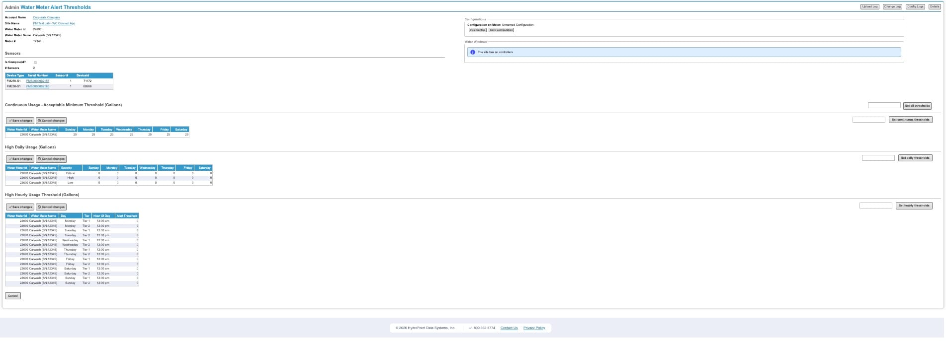
Carwash (SN:12345). The Sensors block shows both linked FM250s; the three threshold groups apply to the combined consumption.Sensors block
At the top, the Sensors section confirms the pair: Is Compound? is set and # Sensors: 2. The table lists both devices (Device Type, Serial Number, Sensor #, Device Id) — in the example, FMS0000002157 (Device 71172) and FMS0000002180 (Device 69568). Each Serial Number is a link; selecting it drills into the combined compound meter device details.
The three threshold groups
Each group has its own Save changes / Cancel changes buttons and a quick “Set … thresholds” helper to fill a value across the row. All values apply to the combined compound consumption.
- Continuous Usage — Acceptable Minimum Threshold (Gallons): a per-day value (Sunday–Saturday) for continuous-flow detection.
- High Daily Usage (Gallons): per-day values across three severity rows — Critical, High, and Low.
- High Hourly Usage Threshold (Gallons): values by Day, Tier (Tier 1 / Tier 2), and Hour of Day.
The Configurations panel (top-right: View Config / Save Configuration) lets you save the threshold set as a named configuration on the meter.
KEY POINT
Because Is Compound is set, every threshold here is evaluated against the summed low-flow + high-flow consumption on each hourly cloud upload — you configure one set of thresholds for the compound meter, not separate thresholds per FM250.
SECTION 10
Troubleshooting
| SYMPTOM | LIKELY CAUSE | RESOLUTION |
|---|---|---|
| No Link Devicebutton; banner still says “Assign this device to a water meter” | Low Flow device not yet saved with a Monitoring Point | Complete Part A and Save. Link Device appears only after a successful save. |
| Partner device not found in the Link dialog search | Wrong SN, or the partner has not communicated yet | Re-check the serial; confirm the high-flow device is installed and reporting. Search by SN or Device ID. |
| Installer set it up as one device | Single-device install via the Installer App | Do not attempt the manual fix. Escalate via the existing Engineering escalation path; engineering will combine the meters server-side without losing calibration data. See Section 06. |
| High Flow side blank on the Compound Meter Device Details page | Part C not done yet | Expected right after linking. Complete the High Flow Monitoring Point details and calibration (Steps 11–12). |
| Combined consumption looks wrong / doubled / halved | Low/High assignment swapped, or a register mapped to the wrong physical meter | Confirm which device sits on which physical register; correct via the device records (avoid unlinking — see note). |
| Device details record looks wiped after an unlink | Unlinking clears the device-details record (expected behaviour) | Re-run the full setup (Parts A–C). Only unlink if absolutely necessary. |
| Replaced device shows blank calibration (K Value / Gallons per Pulse) | Expected — Replace transfers details and history but not calibration | Calibrate the new device using its install record. See Section 05 Step 7. |
| Customer expects near-instant leak alerts | Hourly comm interval (expected) | Re-set expectations: ~62 min worst case, ~32 min average. Not a fault. |
SECTION 11
Field & term glossary
| TERM / FIELD | MEANING |
|---|---|
| Compound meter | Water meter with two measuring elements (low-flow PD + high-flow turbine) in one service. |
| FM250-S1 | Single-magnetometer flow monitor with built-in LTE cellular. Two are used per compound meter. |
| FM200 | Legacy dual-sensor magnetometer being deprecated; replaced by the two-FM250 solution. |
| Monitoring Point | The water-meter entity the customer sees. A shared Monitoring Point across two devices = the compound meter. |
| Sensor Position | A device's role in the dialog: Low Flow or High Flow. The two paired devices are complementary. |
| Is Compound | Compound aggregation flag — set automatically by the linking process. |
| Link Device | Button in Compound Meter Setup (after save) that opens the dialog to pair a partner FM250. |
| Unassign | Removing a device's Account, Site, and Meter so it can be linked as a compound partner. |
| Unlink | Breaking the compound pairing. Clears the device-details record (full re-setup required) and leaves calibration with the original Monitoring Point — only unlink if absolutely necessary. |
| K Value / Gallons per Pulse | Per-device calibration; never merged. Only consumption is summed. |
| Manage Alerts | Top-right action on the Compound Meter Device Details page; opens threshold/alert configuration. |
| Replace This Device | Button on the Edit Device Details page that swaps an old FM250 for a new one while preserving Monitoring Point, install info, and consumption history. Calibration is not transferred — the new device must be calibrated after Replace. |
FM300
Accordion Body
FM350
Accordion Body
Configurations
Cooling Tower Setup
Accordion Body
Advanced Tasks
Usage Group setup
Accordion Body
Site Group setup
Accordion Body
Replacing a device in Admin
Accordion Body
Moving a Meter
Accordion Body
Accordion Title
Accordion Body