
Overview
After the WaterCompass Control has been installed and connected to the building's ball valve, the flow monitoring system must be configured using the WeatherTRAK Admin Tool.
Pre-Requisites
Before beginning the setup, ensure you have the following:
- A HydroPoint Admin login – Admin-level permissions are required to access the Admin Tool.
- The serial number(s) of the device(s) being configured.
- Access to the target account must be enabled. For new accounts, see the appendix for permission settings.
Glossary
- Data Collector
The device that receives data from the flow sensor and transmits it to the cloud. - Flow Sensor
Measures water flow through a pipe and sends data to the Data Collector. - Ball Valve Decoder
A decoder specifically designed to control the building's internal ball valve.
Step 1: Assign the Data Collector (Controller)
- In the Admin Tool, go to the Controllers section from the home screen.

- In the Controller List, search for the Data Collector using its serial number.
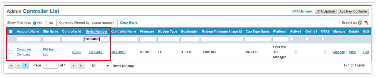
- Click Edit on the appropriate device entry.
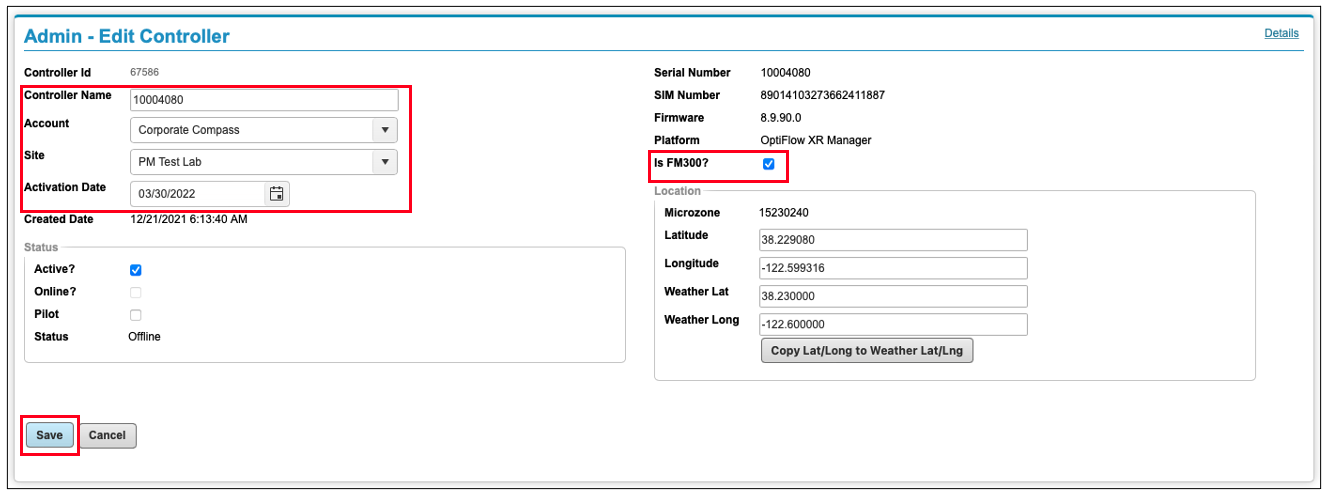
- Assign the following:
- Account: Choose from the dropdown.
- Site: Select the relevant site.
- Activation Date: Set accordingly.
- Check the box labeled Is FM300?
- Click Save to assign the Data Collector to the specified Account and Site.
Step 2: Configure the OptiFlow Hydraulic Tree
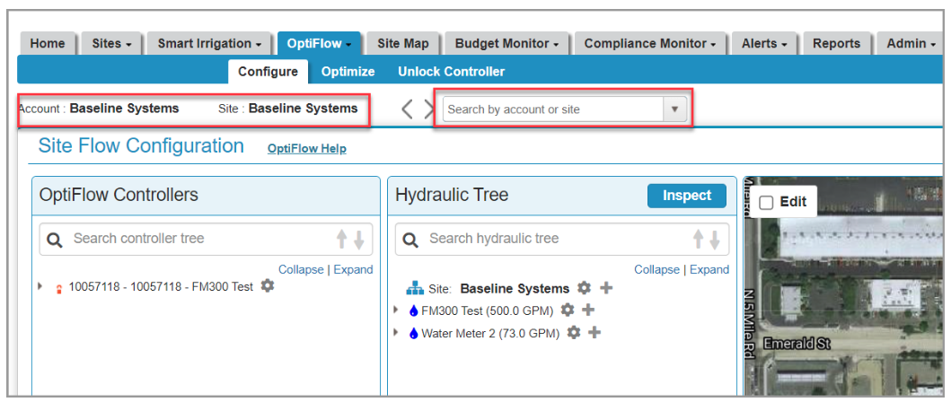
- Go to WeatherTRAK Central > hover over the OptiFlow tab > select Configure.
- Ensure you are viewing the correct site. Use the search box near the Account/Site name to switch if necessary
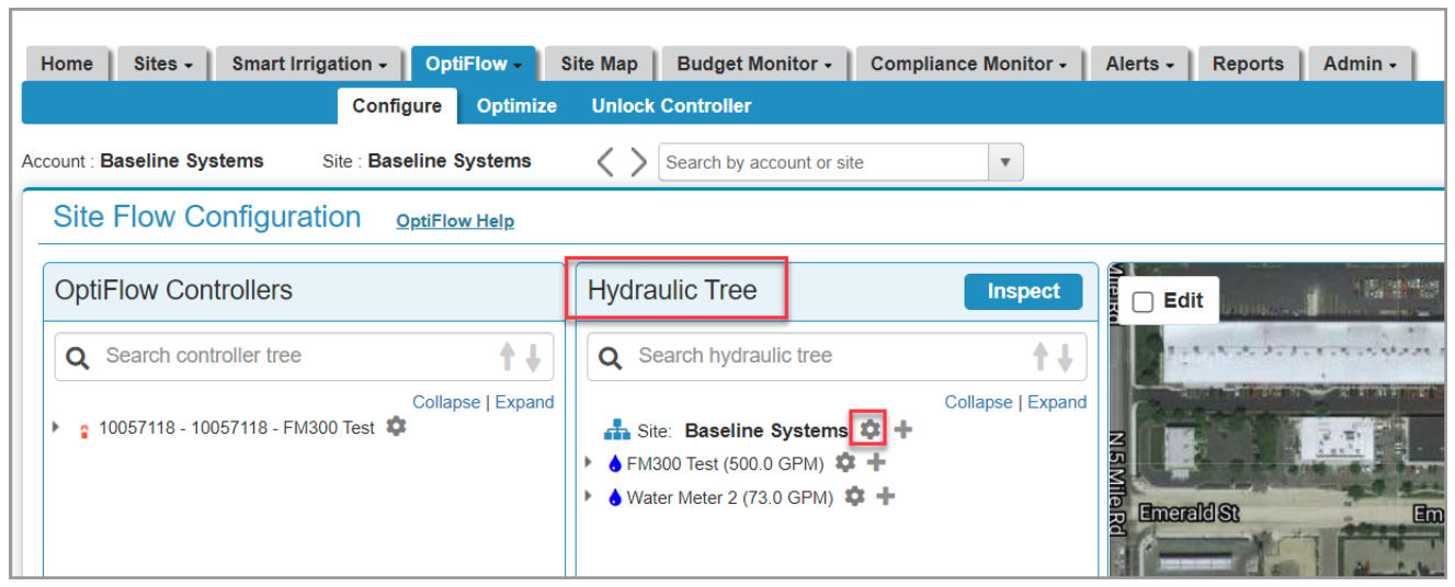
- In the Hydraulic Tree panel:
- Click the gear icon next to the site name to open the Site Settings Menu.
- Click Edit Site Settings.
- Set the Time Zone.
- Set the Irrigation Window from 12:00 AM to 10:00 PM.
- Click Save.
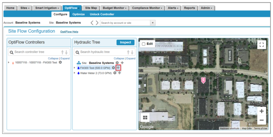
Add Water Source
- Under the Hydraulic Tree:
- Click the + icon next to the site name to add a new Water Source.
- Name it (e.g., use the site or Data Collector name).
- Skip the Max GPM Calculator section.
- Set Max GPM to 1000 (placeholder value).
- Click Save.
Add Mainline Pipe
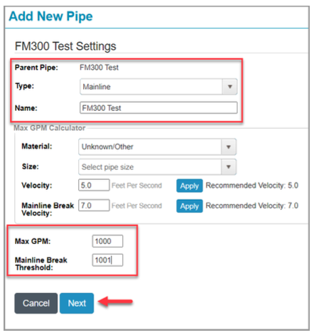
- Click the + icon next to the Water Source to add a Mainline Pipe:
- Set Type = Mainline.
- Name the Mainline (e.g., same as Water Source).
- Skip the Max GPM Calculator section.
- Enter:
- Max GPM = 1000 (placeholder).
- Mainline Break Threshold = 1001.
- Click Next.
Configure Point of Connection (POC)
- In the Edit Mainline Details view:
- Click Add POC.
- From the Point of Connection dropdown, select the Data Collector using its serial number.
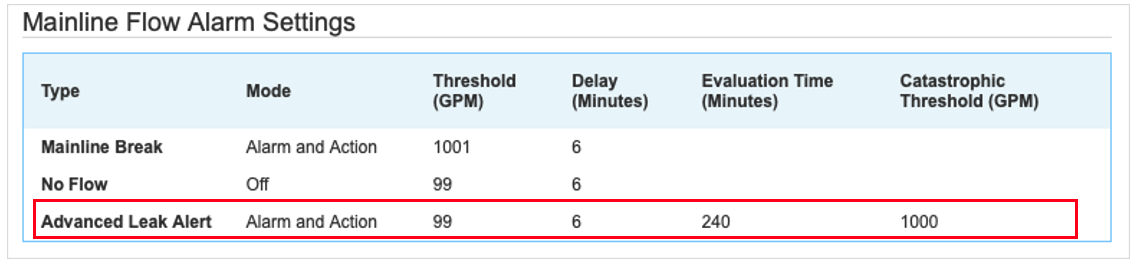
- Set the Advanced Leak Alert settings:
- Threshold (GPM): 99
- Delay (min): 6
- Evaluation Time (min): 240
- Catastrophic Threshold (GPM): 1000
POC Settings
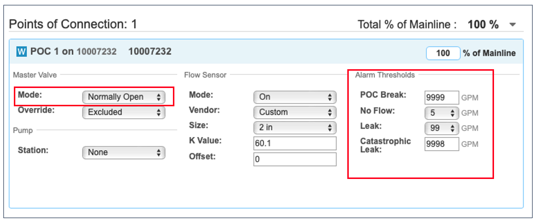
- Under POC1:
- Set Master Valve Mode to Normally Open.
- Turn Flow Sensor Mode to On.
- Set Vendor to Custom.
- Verify:
- Vendor details
- Flow sensor size
- K-value
- Offset
- Fill in Alarm Thresholds
- POC Break: 9999 GPM
- Leak: 99 GPM
- Catastrophic Leak: 9998 GPM
Step 3: Create a Water Meter
- In HPDS Admin Tool, hover over the Budget Monitor tab and select Water Meter List.
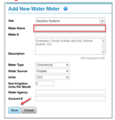
- Click Add New Water Meter.

- In the Meter Name field, enter a descriptive name and click Save.
Important: Do not assign the controller to the water meter on this page.
Step 4: Configure the WaterCompass Device
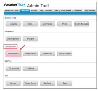
- Open the Admin Tool
Navigate to the WaterCompass section and select Water Meters.
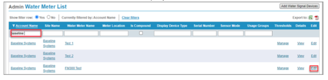
- Locate the Device
Use the search bar to find the WaterCompass device by entering its serial number.
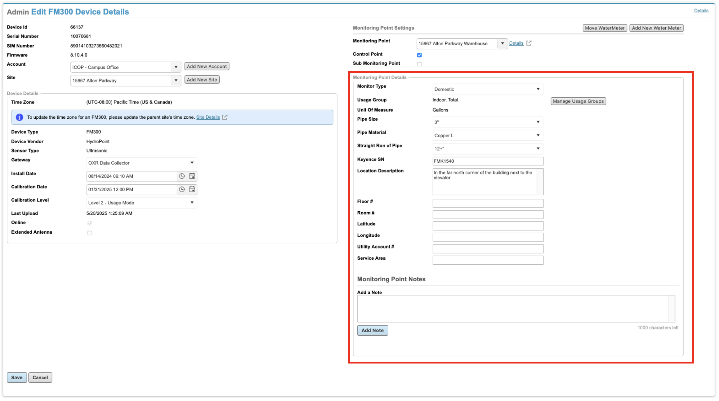
- Assign Device Settings
- Select the appropriate Account.
- Choose the correct Site.
- Assign a Monitoring Point.

- Set Control Point
In the Monitoring Point Settings, check the box labeled Control Point.

- Complete Monitoring Point Details
Fill in all required fields in the Monitoring Point Details section to complete the setup.
- Configure the Usage Group
Assign the device to the correct Usage Group.
This step ensures that water usage data appears in the appropriate bucket on the customer-facing dashboard.
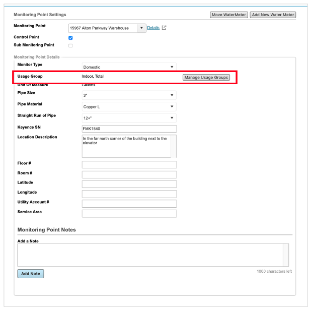
Note: Selecting the correct Usage Group is essential, as it determines how water usage data is categorized and displayed in the WaterCompass Dashboard.
For FM300 Flow Control devices, the recommended selections are typically Indoor Usage and Total.
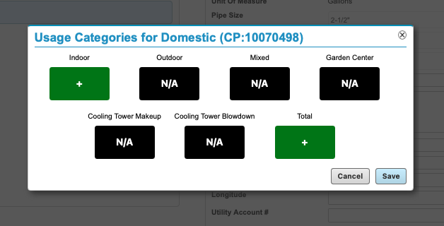
- Click Save.
Step 5: Verify Control Point Setup in Admin Tool
To ensure the system is properly configured and ready for valve control:
- From the Admin Tool Home, navigate to the Control Point section.
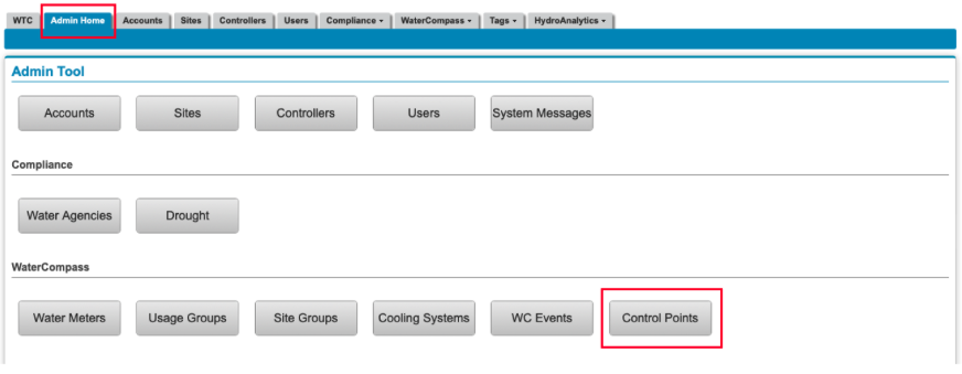
- Locate and verify that the Control Point is properly configured with the expected settings and assigned device.

Step 6: Verify Control Point Access in WaterCompass.net Dashboard
To confirm that the customer has visibility and remote control access:
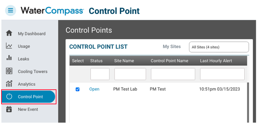
- Log in to WaterCompass.net and navigate to the Control Points page.
- Verify that the Control Point appears and is accessible on the dashboard.

© Copyright 2025 HydroPoint Data Systems, Inc. All rights reserved. HydroPoint, the HydroPoint logo, and WaterCompass are either registered trademarks or trademarks of HydroPoint, Inc. Other trademarks may be held by their respective owners.