
 | |
 | |
 |
y• HydroPoint”
INTRODUCTION................................................................................ 1
INSTALLATION AND CALIBRATION OVERVIEW....................... 1
Number of Visits to Install the FM200................................ 4
EQUIPMENT LIST......................................................................... 5
FM200 Install Kit.................................................................... 5
Equipment Needed............................................................... 6
Safety Equipment.................................................................. 7
Materials................................................................................. 7
MOBILE/WEB APPS THAT WILL BE USED................................. 7
The Forms App....................................................................... 7
FM200 Activator App............................................................ 8
A Tale of Two Apps................................................................ 8
INSTALLING THE HARDWARE.................................................... 8
PHASE ONE – INSTALLATION......................................................... 9
USING THE FORMS APP.............................................................. 9
CUSTOMER AND INSTALLER INFORMATION........................ 10
SITE INFORMATION.................................................................. 10
FM200 INSTALLATION.............................................................. 10
Mount theAntenna............................................................ 11
Mount the FM200............................................................... 13
Installation in a Deep Vault................................................ 14
Installation in a Small Box.................................................. 15
Installation Above Ground................................................. 15
Installation to an Indoor Suspended Meter.................... 16
Attaching the Antenna....................................................... 16
Water Meter Types............................................................. 17
Attaching a Sensorto the Water Meter.......................... 19
Attaching the Sensorto a Flat Meter............................... 21
Attaching a pulse cable to the FM200............................. 22
Proper Cable Maintenance................................................ 23
Finishing Phase One............................................................ 23
PHASE TWO – POWER UP............................................................ 24
PHASE THREE – SIGNAL TEST...................................................... 29
PHASE FOUR – INITIALIZATION.................................................. 31
PHASE FIVE – SENSORPAIRING.................................................. 34
PHASE SIX – BASE READING........................................................ 37
PHASE SEVEN – CALIBRATION READING.................................. 38
PHASE EIGHT – VERIFICATION READING.................................. 39
OTHER INFORMATION ABOUT SITE OR INSTALL.................... 39
CUSTOMER APPROVAL................................................................ 39
REVIEW YOUR WORK................................................................... 39
BEFORE LEAVING THE SITE.......................................................... 39
Form Submission................................................................. 39
PHASE NINE – CALIBRATED......................................................... 41
TROUBLESHOOTING..................................................................... 42
Alternative AntennaPlacement........................................ 42
Checking Battery Connections.......................................... 44
Communication Error Codes............................................. 45
No Pulses – PulseWire....................................................... 46
No Pulses – Sensor.............................................................. 47
Power Up.............................................................................. 48
MAINTENANCE.............................................................................. 49
BATTERY REPLACEMENT......................................................... 49
Before replacing the FM200 battery................................ 49
Replacing the FM200 battery............................................ 49
After replacing the FM200 batteries................................ 54
GLOSSARY....................................................................................... 55
Introduction
The HydroPoint WaterCompass service provides real-timemonitoring to enable leak detectionand water conservation. The service uses an onsite flow monitor to constantly gather water usage data, synchronizethat data to the cloud, and analyze it to provide visibility into consumptionand to enable monitoring and alerts.
This installation and service manual is intended to detail the process acontractor should follow to install an FM200 Flow Monitor onsite, as well asoutlining the troubleshooting and maintenance steps necessary by on-site staff to keep the unit providing qualitywater usage data over time.
The FM200 Flow Monitor is a non-invasive flow monitorthat reads usage data from the existingonsite water meter,continuously watches forleaks, and tracks ongoing water usage.
You don't need to turn off the water or cut any pipes toinstall the device. Afterinstallation, the monitor will beable to read pulses from the watermeter and establish a cellular data connection to upload usage data to theWaterCompass service.
The majority of this guide will focus on installing theFM200 at a new site (or ensuringa previously installed device was installed/configuredcorrectly. If you have any questions or issues while installing the FM200,please call Contractor Support at +1 707 285 3250 for assistance.
Installation and Calibration Overview
The installation and calibration process consists of ninedistinct phases, during which you will be assisted by two mobile applications:
· TheForms app from Device Magic, which isused to provide forms input andupload photographs of the installation
· TheFM200 Activator app, which provides you with the latest FM200status information from HydroPoint servers.
The installation and calibration phases include:
1. Installation – Mounting the FM200 and its antenna near the existing water meter, and fastening the sensor to the meter.
2. Power Up – Waking up the device from itsidle state by swiping a magnet acrossthe device and waiting for a confirmation beep.
3. Signal Test – Verifying the built-in cellular communication bytesting whether the device can communicate with HydroPoint servers under normal conditions.
4. Initialization – Using the FM200 Activator app on your mobile device to initialize theFM200 and swipe the magnet across the flow monitor.
5. Sensor Pairing – Ensuring that water is running as the sensor starts reading pulses from thewater meter then swiping a magnet, taking a photo of the water meter, andconfirming the sensor is properly paired with the meter.
6. Base Reading – Swiping a magnet across the device, and taking a photo of the water meter register(this is referredto as a Reading).
7. Calibration Reading – Ensuring 1,000 gallons (134 cubic feet) flows through the meter afterthe Base Reading,then swiping a magnet across the device and taking a photo.
8. Verification Reading – Ensuring 1,000 gallons (134 cubic feet) flowsthrough the meter after the Calibration Reading,then swiping a magnet across the device again and taking another photo.
9. Calibrated – Getting confirmation from Contractor Support that the flowmonitor is calibrated, which completes the installation.
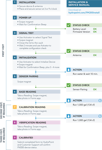
It is importantto track your status againstthese phases, becauseif you encounter anydifficulty, Contractor Support will use these terms and phases to understandwhere you are in the process. They also show the recommended order in which thesteps should be performed for a successful installation and calibration.
Number of Visits to Install the FM200
Ideally, the FM200 should be installed in a single day. But, since a full install requires running at least 1,000gallons (134 cubic feet) of waterthrough the system twice for proper calibration, this may not be possible dueto the inability to run that much water through the system in the time that youare able to be on site.
If you don't have enough time to finish the installationin one day, here is howyou would need to install the FM200 across multiple visits:
Two-Visit Install – Do Phases1 through 6 during the first visit, and save your form in the Forms app at the end of the day. On thesecond visit, start with Phase 7 and complete the installation.
Three-Visit Install – DoPhases 1 through 6 on the first visit, and save your form in the Forms app at the end of the day.On the second visit, do Phase7, the Calibration Reading, and save your formagain. On the third visit, do Phases8 and 9, complete the installation, and submitthe final form.
If you are unable to complete the installation, and adifferent contractor will be finishingthe installation, contact Contractor Support to ensure theform submittal, and the contractor handoff, is handled properly.
NOTE: In some cases,Contractor Support may inform you that the Verification Reading will beperformed by the customer's on-site personnel, or through validation against awater bill.
 |
Equipment List
FM200 InstallKit
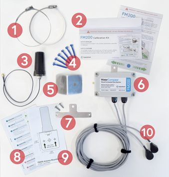
All of the contentsof this kit are included in a single box provided by HydroPoint. The photographbelow shows the parts for a dual-sensor version. Note thatthere are two other versions: single-sensor and single pulse wire. You can tellwhich version you have by the model number on the label on the packaging:
WC-FM200-V-1S – Single-sensor FM200 WC-FM200-V-2S –Dual-sensor FM200
WC-FM200-V-1P – Single pulse wire FM200
The following numbers correspond with the numbered imageson the photograph below, displaying everything that is included with the FM200Install Kit:

Hose clamps


FM200 Calibration Kit (which includesa magnet) EM Wave antenna


Six 3/16" x 1 1/4" self-tapping concretescrews Antenna mount

FM200 Flow Monitor


Additional FM200 mounting bracket FM200 Installation & Calibration Overview Antenna mounting template

Intelligent sensor with 12-foot cable
Equipment Needed
You will need to arrive on-site equipped with these tools:
· 5/16" nut driver
· 3/16” masonry screw bits for drill
· Cable ties (long)
· Cordless hammer drill
· Cordless impact driver
· Flashlight
· Hand pump (or some way to remove water from thevault)
· Ladder (six-foot)
· Magnet
· Mobile phone (iOSor Android) with data service
· Scissors
· Screwdrivers (flathead, #2 Phillips head,and precision/jeweler's)
· Trowel (small,in case of dirt in ground vaults)
· Wire cutter
· Wire stripper
Safety Equipment
· Bug spray (not repellent)
· Ear protection
· Eye protection
· Gloves
· Hard hat
· Knee pads
· No-slip work shoes
· Safety vest
Materials
You shouldalso have the following materialsand parts with you:
· Double-sided tape
· Hose clamps, for pipe sizes from 6to 12 inches in diameter
· Irrigation valve box (8 inchesround, optional, needed only if theantenna needs to be externally mounted)
· Loctite® GO2 Glue
· Tapcon® 3/16" x 1 1/4" Self-Tapping Concrete Screw or equivalent
· Towels and wipes
· Velcro® strips, 24-inch long
Mobile/Web Apps that Will Be Used
· The Forms appby Device Magic (iOS or Android)
· FM200 Activator(web-based, mobile-friendly)
The FormsApp
 |
The Forms app from Device Magic will guide installersthrough every step of the on-site installation, so you can record the detailsof the installation process that are required by HydroPoint to deliver services, and ensure that all necessarysteps are performed.
You will document the state of the equipment as you arrive, and capture how it is left as you finish.
If you are the designated installer, you should receive an emailinvite to install the app. If you didn't receive an invitation, contactContractor Support.
The email message will contain links to download the appfrom either the App Store (for iOS) or on Google Play (for Android), as well as instructions on howto sign in to the HydroPoint team. You should join the team before going onsite, asyour request has to be approved before you can access the form.
You should be able to log into the Forms app, and open the "WaterCompass Installation" form before you go to thesite.
FM200 Activator App

The FM200 Activator app will guide you throughcalibrating the equipment you just installedto make sure it is working properly. It can be accessed through a webbrowser, and can also be opened directly from the Forms app.
The FM200 Activator is not an app in the traditional sense, but rather amobile-responsive website you access at activate.watercompass.net. You willneed your weathertrak.net login credentialsto access the Activator. If you do not have a WeatherTrak account, please contact Contractor Support.
A Tale of Two Apps
The best way to think of the two apps is that the Formsapp from Device Magic will be your real-time checklist while you are on site,telling you what information to record, and providing you with a wayto track the sequence of things to do on site to properly install the device,document the critical data HydroPoint needs to configure the device, andrestore the site how you found it.
The FM200 Activator App is what you will use to test,tune, and interface with the FM200 device and HydroPoint serversthroughout the installation phases.
Installing the Hardware
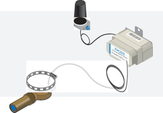
This installation video addresses how to mount the FM200 inside of a vault, because that is the more complicatedinstallation. The meter may also be installed on an exposed wall orfreestanding pipe.
Note: The installation video is available at: https://hydropoint.com/watercompass/installvideo
Before you go onsite, you should watch this videoat least once, if you haven’tpreviously installed an FM200 Flow Monitor.
Phase One – Installation
Using the Forms App

The Forms app from Device Magic will guide you throughthe essential steps in the installation process. You will enter informationinto selected fields as you work your way throughthe install. The information you enter will then beuploaded to the cloud to synchronize important water meter data. It
is important to fill out every applicablefield throughout this process.

Open the Forms app and the followingscreen will display:
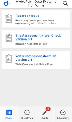 |

Tap the WaterCompass Installationform. Six different sections will display.You will need to open each section as you go through the process to successfully complete theinstallation, although the form may be completed and saved over multiple visitsbefore submitting:
§ Customer and Installer Information
§ Site Information
§ FM200 Installation
§ Other Information About Site or Install
§ Customer Approval
§ Form Submission

Work through each section and fill in all applicablefields. In some cases, portionsof this form will also be pre-populated with the correct information.
Below are descriptionsof what needs to be completed withineach section of the app.
Customer and Installer Information
Customer Name: The name of the customer(or business) for whomyou are installing the device.
Installer Information: Your name, email address, and phone number.
Escorted by: The name of the person escorting you to the site, ifapplicable; otherwise “N/A”.
Site Information
Enter the Site Name, Address, City, State and Zip Code.
Capture the site GPS locationwith your mobile deviceby tapping the compass icon.
Take a photo of the site by tapping the camera icon. It is recommended that youtake an exterior shot of the site that shows buildings and surroundings as thiswill be used on the cover of the report. Itis intended to be an attractive view, and shouldbe taken as a landscape/horizontal view.
FM200 Installation

Tap the Calendar Icon to select the date and time you began the install.
Tap the + icon (Add Item) to begin.
The Meter Name/Number field will be automatically populated. You do not need toadd anything.

Meter used for: Tap to selectthe appropriate choice. If unsure, test whether the meter registersif a sink is turnedon, irrigation is turned on, or both. Select unknown ifunable to determine.

Take a photo of the water meter with the vault closed. Make sureto clearly show the vault doors and the surrounding area.

Take a photo of the water meter with the vault open. Make sure to clearly show the interior of the opened vault.

Take a photo of the water meter register and surrounding area. Make sure that theregister lid is open,and that the area around the meter can be seen.

Capture the GPS location of thewater meter with your mobile device by tapping the compassicon.

Water meter locationdescription: Describe where the watermeter is located on the site.

Enter the brand, model, size and serial number of the watermeter. This is usually found on the face of the meter. You may also want totake a photo of the serial number of the FM200 now, in case you install it where it maybe difficult to read later.

Enter the units that the water meter is read in and the current water meter reading. The unit of measure is located on the face ofthe meter register and will indicate whetherthe water meter reads in gallons, CF,or CCF. If unable to determine, call Contractor Support to troubleshoot.

Mount the FM200 device andantenna. See Error! Reference s ource not found. below for moreinformation.

Enter the serialnumber of the FM200 device. This numberis found on the barcode and begins with a P.
Mount the Antenna
The antenna should be the first thing you install, especially if spaceis tight near the water meter.If you mount the FM200 first, it may get inthe way of installing the antenna.
Identify where to mount the antenna
You should try to position the antenna as high in theutility vault or meter box as possible, but still be able to close the lid ordoor to the meter location. It also needs to be within two feet of the FM200,so the cable can reach. Both theFM200 and antenna are designed to be waterproof, but if theantenna is submerged under water, it will not communicate.
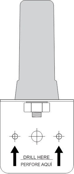
The antennashould be mounted vertically, with the tip of the antennapointing up. A template is available in the kit to make this process easier.You can also find it as the last page of this guide or a downloadable PDF isalso available online at http://www.hydropoint.com/watercompass/antenna-template.pdf. If you print the template yourself, besure that you print it without scaling; a ruler is included on the template tocompare with a tape measure.
1. Tape the templateincluded in the FM200 kit to the location where you want to position theantenna (do not use this image):
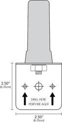 |
2. Drill starter holes through the templateusing a 3/16” drill bit.
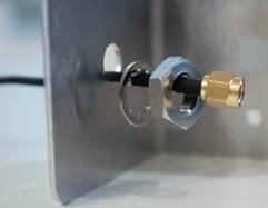
3. Unthread the nut from the antenna.
4. Feed the antenna cable through the hole ofthe mounting bracket and secure theantenna to the bracket:
 |
The properposition is with the bracket oriented as an upside-down “L”, with the portion that is screwed into the wall below the antenna.
5. Screw the mounting bracket to the surfaceusing the 3/16" x
1.25"Self-Tapping Concrete Screw included with the FM200 Install kit.
Mount the FM200
Assess the vault layoutwhere the meter is located to determine the bestlocation to install the FM200 Flow Monitor.
The unique location of your water meter will determinewhere you need to install the FM200 device.It can be strapped to a pipe, or onto a wall, or anywhere elsethat gets the device close enough to the meter to attach the sensor andantenna. Based on the meter location and available space, the FM200 can beinstalled vertically or horizontally.
You should try to mount the FM200 device as high as possiblein a utility vault or mechanical room to prevent water submersion.
Although theFM200 plastic enclosure is rated for submersion, it will not communicate if the antenna issubmerged.
If the water meter is located in a shallowmeter box, the FM200 can sit on the ground, with the antennamounted inside the box or staked intothe ground inside the box.
Installation in a Deep Vault
There are specialconsiderations when installingin a deep vault. In somecases, this vault may be defined as a "confined space," specificallyif the interior is deeper than five feet below grade.
IMPORTANT: All work performed inconfined spaces is subject to additional performancerequirements, including at least two installers – withconfined-space certification – and the proper equipment to complete the scopeof work. These jobs need to be planned sufficiently ahead of time, as it willaffect equipment, personnel (certification and training), scheduling, and logisticalrequirements.
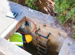
If the water meter is in a deep vault of any type, the best mounting location is near the top,just below the lid. In the photo below, the FM200 Monitor andantenna are within the red circled area.
 |
Installation in a Small Box
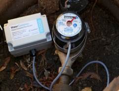
If the water meter is in a smallbox, the best option is to lay the FM200 Monitor at the bottom of the box,with the antenna mounted to the side, close to the lid.
 |
Installation Above Ground
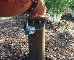
If the water meter is above ground,you will not have access to a utilityvault or box to house the FM200 flow monitor. Due to this, you will need tohose clamp the flow monitor to the inside elbow of the water meter. This willprovide a small amount of protection from vandalism or theft.
 |
Installation to anIndoor Suspended Meter
Some indoor submeters are located in mechanical rooms orutility closets, often suspended8-15 feet in the air. This makesmounting the FM200 flowmonitor to a nearby wall difficult given the length of the sensor cable. Inthis type of installation, you can use the second device mounting bracketand an extra hose clamp toattach the FM200 directly to the pipe feeding the water meter.

Flip the device overto attach the additional mountingbracket, opposite to the existing bracket.

Use two self-tapping screws to attach the bracket directly to the device enclosure. There are two holes already available.

Feed a hose clamp between the FM200 enclosure and the twomounting brackets attached to the FM200 device. Depending on the pipe size, you mayhave to use a larger hose clamp from your materials inventory to attach theFM200 to the pipe.

Once the hose clamp(s)are fed through the mounting brackets, you can attach it to the pipenear the water meter.

Tighten the hose clampwith a flathead screwdriver or 3/16” nut driver. Based on availablespace, you can mount the FM200 to the top, side, orunderneath the pipe. Be sureyou have enough cable to run to boththe sensor and antenna from this location.

Once the hose clamp is secure, ensure the FM200 does notwiggle or move around. It shouldfit snuggly against the pipe.

You can now connect the antenna, sensor,and continue with theinstallation.
Attaching the Antenna
Once theantenna and FM200 are mounted, you can connect the antenna to the FM200.
1. Removethe yellow plastic dust cover from the SMA connector, which is located on theleft side of the FM200:
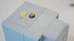
2. Thread the antenna onto the SMA connector and tighten as tightas possible by hand. Do not overtighten with a tool, as this may affect theconnections inside the FM200.
Water Meter Types
Another important step in installing the FM200 is todetermine the type of watermeter on the site. It will eitherbe a single or dual watermeter and use either magnetic sensorsor pulses to read the amount of water flowing through the system.
You shouldalready have the appropriate version of the kit to match the size and type of water meter at your location, but tomake sure here is how to tell them apart:
Single Water Meter
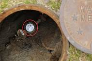 |
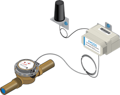
A single water meter has one visible display. The oneshown has no cables coming from the meter, which means it must use magneticcouplings. This meter would usea single-sensor version of theFM200.
Compound Meter (2 registerson a single meter)
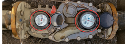
A compound meter combines a high-and low-flow register in the same water meter. This type of water meter requires the dual-sensorversion of the FM200.
A dual-sensor device can also be used in locations where there are two adjacent water meters near each other, such as one for mixed useand another specifically for irrigation.
In this case, the installation of the FM200 and antennawill be the same, but you will need to attach a separate sensor to each meter,and clearly indicate with photosand in your Forms app notes, which sensor is attached to which meter.
When using dual sensors, one will be marked with an “S”and one with an “B”. This stands for “small” and “big.” Be sure to attach thesensor with the S on the low-flow side, andthe sensor with the B on the high-flow side.
To figure out which is the high- and low-flow side, thesize of the meter is located on the face of the meter register. The low flow is the meter register with the smaller pipesize, while the high flow is the meter register with the larger pipe size.
Pulse OutputMeter
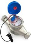
If there is an unusedcable coming out of the meter, it could potentially be a pulseoutput meter. If this is a water utility meter, you should still install thesensor, unless the onsite water meter is specifically a Sensus Omni meter.Verify the make and model of the meter on its register.
IMPORTANT: The utility-owned Sensus
Omni is a special case, and will have 2 color cables, onewhite and one black. The white cable is a PulseOutput, and you can install an FM200pulse device to a utility-owned Sensus Omni meter with the
white pulse cable.Do not disturb the black cable, even if it isnot connected to anything in the utility vault.
If this is a customer-owned submeter, you should installa pulse version of the FM200 FlowMonitor as described in Attaching a Pulse Cable to the FM200 below.
Kit Verification
At this point,you should verify that the versionof the FM200 Install Kityou have with you matches the type of water meter on site. If you have thewrong kit, contact Contractor Support.
Attaching a Sensorto the Water Meter

Clean thesurface of the meter’s register with towels or wipes.Remove any dirt or pooled water from around the meter.

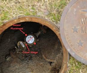
Place thesensor in the 3 or 9 o’clockposition on the meter, withrespect to the top of the meter. Donot install the sensor on the face of the meter.
 |
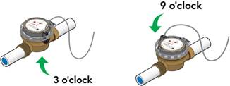

Clean any large debris from around the meter register.
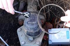 |
Place the FM200 sensor with the side that is marked with an X against the side of the meter. Theteardrop-shaped sensor should be placed as low on the meter register aspossible – where the meter register meets the meter body.

Attach the sensor to the side of the water meter usingthe hose clamp. The cable of the sensorshould come straight up from the water meter body, as shown inthe image below. Tighten the hose clamp as tight as possible (don't worry, youwon't damage it), using a flat head screw driver or 3/16” nut driver. Once
secure, the sensor should not be able to move or wiggle.
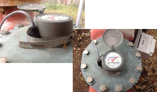 |
Attaching the Sensorto aFlat Meter
If the meter isflat with no place to clamp the sensor, you will need to glue the sensor onto the body of the water meter. Be sure to complete the Sensor Pairing phase to ensure you are installing the sensor in a goodlocation before gluing it down. Do not glue the sensor onto the face of the meter register. The proper location should look more likethis:
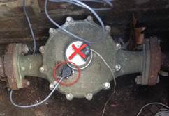 |
Clean the surfaceof the meter where you are attaching the sensor and use double-sided tape to temporarily secure thesensor during this phase.
After you get the sensorto pair, you should glue it down. First, you will have toremove the double-sided tape from the sensor. Then, cover the flatportion of the sensor that connects to the water meter
with a high-quality, outdoor, weatherproof glue. Werecommend Loctite® GO2 glue. Glue does notdamage the sensor, and the sensor can later be removed with a flatheadscrewdriver.
Be sure to position the sensor in theexact same location on themeter body as you had it during Sensor Pairing.
IMPORTANT: You will have to complete the Sensor Pairing phase againonce the glue has cured. Make sure the sensor is not moving on the water meter before completing the Sensor Pairing phase again.
Attaching a pulse cable tothe FM200
If the water meter has a digital pulse output, you willnot have to install a sensor to the outside of the water meter. The FM200 youhave should be a pulse version that includes a 3-wire cable,a small junction box, and apulse jumper.
To wire the pulsecable from the water meter to the 3-wire connector located within a small junctionbox attached to the FM200:
Pull back the cable sheath of the pulse cable on themeter and determine if the pulse cable uses a 2- or 3-wire connection. Thewires will be color coded. If you encounter a pulse cable that has more than 2 or 3 wires,or has an alternate color scheme, please call Contractor Support at+1 707 285 3250 for assistance.
Strip each wire of the 2- or3-wire pulse cable individually, so youcan wire the pulse cables to the terminal block located within the junction box attached to the FM200.

Remove the lid from thejunction box attached to theFM200 with a Phillips headscrewdriver.

Remove the3-wire terminal block from inside the junction box. The FM200 will be pre-wired to theterminal block. You will see three colored wires – black,red, and green – each separately connected to the terminal block.

Unscrew the black waterproof gland from the junction box with your hand.

Feed the pulse cable from the water meter through thewaterproof gland of the junction box. Be sure to feed the pulse cable throughthe loose piece of the gland you removed, as this will tighten around the cable afterit's inserted to maintain waterproofing.

Match andconnect each wire from the pulsemeter to one of the wires alreadyconnected to the terminal block, as described below. Connect each wireindividually and tighten with your precisionscrewdriver before moving to the next wire. You should connect the wires by color as follows:
2- wire
· Black wire from the pulse meter to the blue wire on the terminal block
· Red wire from the pulse meter to the green wire on the terminal block
3- wire
· Black wire from the pulse meter to the blue wire on the terminal block
· Green wire from the pulse meter to the green wire on the terminal block
· Red wire from the pulse meter to the red wire onthe terminal block

After connectingeach wire, push the terminal block back into the junction box and tighten thewaterproof gland. Wait until you have the terminal block situated in thejunction box before tightening the gland completely.

Reattach the lid tothe junction box.

Proceed to Power Up phase of the installation.
Proper Cable Maintenance
Before proceeding to the next phase, you shouldseparately loop the remaining antenna and sensor cables and keep them in placeby fastening them neatly with cable ties.
Finishing PhaseOne
Once the antenna, the FM200, and sensor allconnected and in position, you are ready to proceed to the PowerUp phase. If you have installed the FM200 to a pulsemeter, verify all wire connections are correct and proceed to the Power Upphase.
Phase Two – Power Up
This phasewakes the deviceup from its shipped idle state.
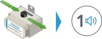
Swipe a magnet across the top of the FM200, near the barcodeand serial number. The device should beep immediately.
Wait until you hear a Confirmation Beep, which can take up to30 seconds, which means the device is communicating with the server.
 |
Note: If you donot hear a beep, or it is emitting more than a single beep,consult the Power Up instructions in theTroubleshooting section.
Status Check: Before continuing, you need to confirm the configuration status of the battery level and that the firmwareis up to date.
To confirmthe battery and firmware status:

Go to activate.watercompass.net on your mobile device(or tap the web address directly from the Forms app) to launch the Activatorapp, which is designed to run on both iOS and Android devices.

Log in to the app using your WeatherTRAK® username andpassword. Tap Continue.
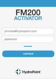

Enter the Serial Number of the FM200 Monitor. This can be found on the barcodelabel.

Tap Search. The site will start lookingfor the serial number you entered.
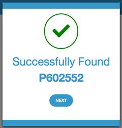
After the site recognizesthe serial number, a messagedisplays, stating that the serial number was successfully found.
Device not found? If theserial number of the device is not found, verify that you have typed it in correctly. If the system is still not able to find theserial number, please call Contractor Support for assistance.
 |


Tap Next.
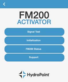
Select FM200 Status from the menu:
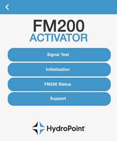
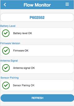
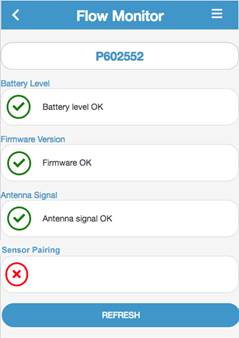
On the next screen you will see four sections: Battery Level,Firmware Version, Antenna Signal, and Sensor Pairing:
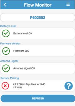
You should see a green checkmark before Battery Level OK and Firmware OK. Theremaining items may have green checkmarksor red x’s; that is not an issue at this time.
If battery level doesn'treturn a green checkmark – Follow the instructions in Check Battery Connections. If after you followthose instructions, and swipe the magnet again, you still don't see a greencheckmark, contact Contractor Support for assistance.
If firmware doesn't return a green checkmark – Call Contractor Support for assistance and they can push the latestfirmware version to the FM200remotely.
To update the firmware:

Swipe the magnet acrossthe FM200 afteryou are told the firmware isready for download. The update will take approximately 20 minutes to complete.

Once complete, the device will provide a singleConfirmation Beep. If you are in a loud or noisy environment, you may wish tobegin refreshing the Activator app after ten minutes, and verify that thefirmware version now has a green checkmark.

If you do not see a green checkmark after20 minutes, contact Contractor Support again foradditional assistance.
Phase Three – SignalTest
IMPORTANT: Read this entire section before you begin.
This phase will test that the FM200 can reliably connect to the nearestcellular tower under normal conditions. Midway through the signal test you will be instructed toclose the vault lid or any doors to the meter location, which is important to make sure that you are still able to get a good signal when thelocation has been returned to what will be its normal operating state.
To test antenna signalstrength:
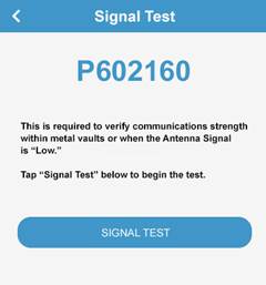
Tap the Optionsicon

at the topright of the Activator app. Tap the Signal Test Option. Thefollowing screen displays:

Tap the SIGNAL TEST button and wait approximately 30 seconds; this is necessary for the serverto flag the device for asignal test.
After swiping the magnet, you will hear a single beep.You have two minutes to return the meter's surroundings to the way it will be afteryou leave, such as closingany surrounding vaults,lids, or doors. This isimportant because it ensures the unitwill be able to communicate undernormal conditions.

The FM200 will attempt to communicate with the HydroPointserver after two minutes. If it successfully communicates, thedevice will beep once, although you may not hear the beep through the closedvaults, lids, or doors.

Tap DONE to leave the Signal Test screen in the Activatorapp.

From the main menu, click FM200Status to confirm the configuration statusof "Antenna signal OK." If you are on the Signal Test screen, tap thearrow in the top left corner to return to theflow monitor configuration.If you closed the Activatorapp and are no longer on this screen, you can access it by selecting FM200 Status from the mainmenu. Refresh the page to update the status.

If the antenna signal strength is good, you will see agreen checkmark after “Antenna signal OK”and you are finished with this step. If “Antenna signal OK”does not return a green checkmark, please refer to the Alternative Antenna Placement section below.
Troubleshooting: Signal Test
If AntennaSignal does not return a green checkmark:
Verify that the antenna is securely attachedto the FM200.
If the antenna is securely attached, relocate the antennato a higher location in theutility vault, as close tothe opening of the utility vaultas possible withoutcreating a safetyhazard. Perform the SignalTest again.
If signal strengthstill doesn't returna green checkmark, you may have toinstall the antenna outside of theutility vault, in a small 8”irrigation valve box. Please refer to AlternativeAntenna Placement for additional details.
Phase Four – Initialization
The next phase in the installation process is to initialize the FM200 Flow Monitor using the FM200 Activator app.
Return to the Activator app and,after entering the FM200 serial number, tap Initialization:
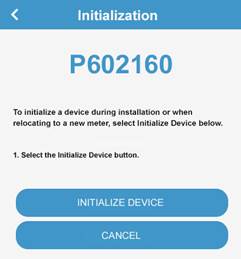 |
Tap the Initialize Device buttonon the following screen:
A dialog will appear, requesting you to swipe the magnet. Take aReading by swiping the magnet across the barcode from one sideto the other, prompting the device to beep, and then immediately take a photoof the water meter register in the Formsapp. Tap DONE.
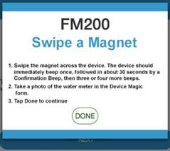

Within approximately 30 seconds of the magnet swipe, youshould hear a single Confirmation Beep, then a brief pause, followed by three or four beeps.If you do not hear any beeps
after waitingfor at least one minute, contact Contractor Support. If you hear a different number of beeps, with analternate tone, refer to Communication Error Codes to determine theappropriate resolution.

Tap Done, which will return you to the Initialize Devicescreen, then tap Next.
Phase Five – Sensor Pairing
Important: For successful Sensor Pairing, water must be flowingthrough the water meter and you must wait approximately ten minutesbefore proceeding.
The next phase in the installation process ensures thatthe sensor is configured properly. With water continuously flowing during this phase, the intelligent sensor willautomatically pair with the water meter. If water is not flowing, the sensor will be unableto pair with thewater meter.
Note: For water meters larger than 4”, meter pairing may take longer than ten minutes.If the sensor has not paired after ten minutes, with water flowing, wait an additional ten minutes. Ifthe sensor has not paired after 20 minutes, please refer to the troubleshootingsection below.
Configuration Check: Before continuing, confirm the configurationstatus of “Sensor pairing OK”:
Swipe a magnet across the top of the FM200. Wait for the beep.

Go to the FM200 Status screen of the Activator app. Ifyou closed the Activator app andare no longer on this screen, you can access it from the main menu.

Verify there is a green checkmark after "Sensorpairing OK." You may have to refreshthe Activator app toupdate the status on the app.
Troubleshooting: Sensor Pairing
If you do notreceive a green checkmark afterSensor Pairing OK, verify that water was flowing throughthe meter during the Sensor Pairing phase.If water was not flowing,the sensor will beunable to pair with the water meter.
If, after a second magnet swipe, you still do not have agreen checkmark, you will need to move the placement of the sensor on the watermeter, because it is mostlikely not getting a strong enough signal from the rotatingmagnet in the meter (if you started in the 3 o'clock position, move it to 4o'clock; if you started at 9, move it to 10), and restart from Phase Four – Initialization again.

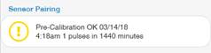
If you see a yellow warning circle with an exclamationpoint instead of a green checkmark(see below), you should swipe themagnet again, as this indicates a discrepancy between today's date and the datewhen HydroPoint last recordedpulses on this device.
Phase Six – Base Reading
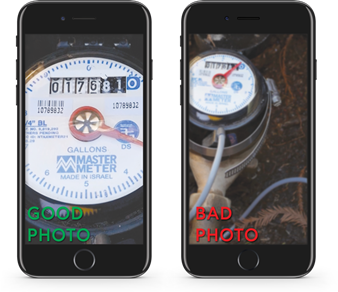
The Base Reading is the first of two snapshots used tomatch the number of pulses received by the FM200 with the actual usage on the water meter register. Take a BaseReading by swiping the magnet across the top of the FM200 and taking a photo ofthe water meter register in the Forms app.
 |
Note: Before you can begin the next phase, you need to waituntil 1,000 gallons (134 cubic feet) of water flows through the meter. Theamount of time it takes for a water meter to push 1,000 gallons (134 cubic feet)of water will vary, basedon the size of the water meter andits end use. In many cases, you will be able to push this amount of water within30 minutes to an hour, by turningon irrigation, sinks,etc. If you do not know what the water meter services, such as domesticor irrigation, you will have to make a judgement call. If the meter ismoving slowly and it does not appear the meter will push 1,000 gallons quickly, an additional visit willbe required.
Phase Seven – Calibration Reading
Important: Before taking aCalibration Reading: At least 1,000 gallons (134 cubic feet) of water needs to flow through the watermeter since the Base Reading.
The Calibration Reading is the second required snapshot tomatch the number of pulses received by the FM200 with the actualusage on the water meter register.
Take a Reading by swiping the magnet across the topof the FM200 and taking a photo of the water meter register in the Formsapp.
Note: Before you can begin the next phase, you need to waituntil 1,000 gallons (134 cubic feet) of water flows through the meter. Theamount of time it takes for a water meter to push 1,000 gallons (134 cubic feet)of water will vary, basedon the size of the water meter andits end use. In many cases, you will be able to push this amount of water within30 minutes to an hour, by turningon irrigation, sinks,etc. If you do not know what the water meter services, such as domesticor irrigation, you will have to make a judgement call. If the meter ismoving slowly and it does not appear the meter will push 1,000 gallons quickly, an additional visit willbe required.
Phase Eight – Verification Reading
Important: Before proceeding to the Verification Reading, another1,000 gallons (134 cubic feet) of water need to flow throughthe water meter since theCalibration Reading.
A Verification Reading is required to ensure that the flow monitorhas been properly calibrated. Take a Reading by swiping the magnet and take a photo of the water meterregister in the Forms app.
You have now completed all of the steps necessary toinstall and calibrate the FM200 FlowMonitor. Before you finish, you will need to provide some additional information in the Formsapp.
Other Information About Site or Install
In the Forms app,record any problems or issueswith the site orinstallation. Tap Edit to begin. Capture a photo and write a description of thesite issue.
Customer Approval
You will need to enterthe name of the customer you are installing the unit for and capturea signature from an on-siterepresentative on your mobile device. Obtaining theirsignature is important, also, because it indicates the customer’sacknowledgment that HydroPoint-owned equipment has been installed on theirproperty.
Review your Work
After completing all fields and beforesubmitting, go back through each item tomake sure information is complete. Double-check the information you added to make sure itis all there.
Before leavingthe site

Clean up all toolsand equipment.
Clean up all trashand packaging from the site. Leavethe site in better condition than you found it.

Verify that the lid or door to the utility meter vault is closed.
Form Submission
After installation, you willneed to sign the form using your mobile device.

Tap the Add Signature button and sign. Tap Save.

Tap the blue checkmark in the lower left corner tosubmit your form.
Note: If information is incomplete, you willnot be able to submit the form. You will get a “Can’tsubmit” error message. Tap the Review Error button to return to the form to complete the necessary information.
Phase Nine – Calibrated
At this point, you should contact Contractor Support at+1 707 285 3250, who will confirm the data and confirm that this FM200 has been properly calibrated. You shouldbe able to reach someone, or get a callback, within 30 minutes. Do not leave the site without waiting that amount of time.
Troubleshooting
In this section, we will outline various conditions whichmay be encountered during an FM200installation, and how you can try to resolve them and keep yourinstallation on schedule.
If you need additional information while troubleshootingany installation issue, you can always call HydroPoint Contractor Support at +1 707 285 3250 foradditional assistance.
Alternative AntennaPlacement
If you were unable to get the FM200 to pass the SignalTest with the lid or doors closed,you may need to relocate theantenna. But before you installan irrigation valve box, you shouldverify communication as follows:
Sit the antennaoutside of the utility vaulton the ground, at the proposed location for the irrigationbox.

Swipe the magnet on theFM200. You should hear an immediate beep upon swiping, followed bya confirmation beep within 30 seconds.

Verify that“Antenna signal OK” has agreen checkmark in theActivator app.

If Antenna Signal returns a green checkmark aftercompleting these steps, installthe antenna in the irrigation valve box at the intended location.

If Antenna Signal does not return a green checkmarkafter completing Step 3, call Contractor Support for additional assistance. A new FM200 may be required to complete the installation.
If the antenna cannot communicate with the cellularnetwork with the lid closed, but it cancommunicate with the HydroPoint servers withthe lid and doors open, you’ll have to relocate the antenna outside ofthe vault. After you get theapproval and permission from the property or vault owner, you willneed to:
Drill a hole throughthe side of the vault where the meter is located.
Run theantenna cable through the hole and reconnect it to the FM200. A cable extension is available upon request if you have to move the sensor morethan three feet away from the flow monitor.
Install an 8” round irrigation box next to the concretevault and stake the antenna into the ground within the box using the L bracket.
Perform the steps of the Signal Test phase again.
Checking Battery Connections
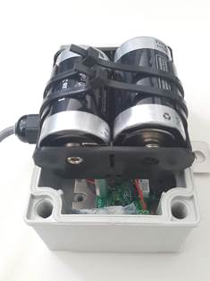
When you are on site, if you donot hear any beeps when running the magnet over the barcode of the FM200,there may be an issue with the battery connections. You will need to open thedevice and check the battery connections.
On-site Resolution
Using a #2 Philips screwdriver, remove the four corner screws that attach the cover to the FM200device.
Verify that the positive and negative terminalsof the battery are correctly installed in the battery holder.

Secure the batteriesin the battery holder using two zip ties, if they are not already.
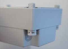
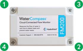
Secure the lid, tightening the screws using thecross-connection pattern shown in the image below, moving slowly from one toanother, in this pattern, then around again, until all are tightened. This will ensure an equalamount of pressure is applied to maintain the integrity of the FM200 enclosure,making it water- resistant.
 |
Communication Error Codes
If the flow monitor is having troublecommunicating after swipinga magnet, the FM200 will emita series of error beeps, indicatingthe modem was unable to communicate with the cellular network or server.
Error beeps sound different from the beeps that areemitted during the initialization process or when a magnet swipe occurs – communicationerror codes occur in immediate succession, at a lower tone than the beeps that occur during theinitialization.
Communication error beeps occur quickly, so you maysometimes have to swipe the magnet again, listening intently for the beeps. Note that there can be up to a two-minutedelay between the magnet swipe andthe communication error codes emitted by the FM200.
Count the beeps in successionas they occur. Feel free to repeat the process as many times as necessary, until you feelcomfortable you have the beep count correct.
Based on the numberof beeps, take the appropriate action:
· 2 beeps - Serveror network error.Try again in five minutes.
· 3 beeps - Servererror. Try again in fiveminutes.
· 4 beeps - Network error. Try again in five minutes.There are two occasions, however, when the FM200will emit four beeps:
During initializationand when played as a communicationerror code, the tone of these beeps, the sequence, and the rate will vary as follows:
Initialization: beep beep-beep-beep-beep(the device will immediately beep once when the magnet is swiped, once for theconfirmation beep, and then three or four initialization beeps)
Communication Error:beep-beep-beep-beep (beeps will occur in immediate succession, no pausesbetween beeps)
· 5 beeps – Antenna-related. Troubleshoot the antenna connection andsignal strength, and try again.
· 6 beeps - No response from the modem. Replace the FM200 device.
If you continue to receive communicationerror codes after three attempts, you should call Contractor Support foradditional support. A new FM200 maybe required to complete the installation.
No Pulses – Pulse Wire
When on site, the FM200 Activator App may show that theFM200 is not receiving pulses from the pulse wires when water is flowingthrough the water meter.Note that, in some cases, if the FM200 Flow Monitor has stopped collecting pulses, the watermeter may be the issue and not the FM200; refer to the troubleshooting sectionon Broken Water Meters for more information.
On-site Resolution

Determine if the pulse cableis cut or otherwise compromised. If it is, and you areunable to re-splice it to the pulse cable outputfrom the meter, then you will need to request a replacement FM200 from Contractor Support and perform a newinstallation.

Verify the 2- or 3- wire pulse cable from the water meteris connected to the FM200 correctly. Based on the type of wire coming from thewater meter, the followingconfigurations could apply:
· 2-Wire cable: The black wire from the water meter will connect to the blue wire on the FM200. The red wire from the water meterwill connect to the green wire on the FM200.
· 3-Wire cable: The black wire from the water meter will connect to the blue wire on theFM200. The red wire from the water meter will connect to the red wire on theFM200. The green wire from the water meter will connect to the green wire onthe FM200.

If you encounter a pulse wire set with a different colorconfiguration, please call Contractor Support for additional support. Beprepared to provide photos of the color configurationof the cable, which will assist them in providing troubleshooting steps. They will provide you with instructions on what to do,which may includesending photos while you are on-site to activation@hydropoint.com, with the site name asthe subject.
No Pulses – Sensor
When on site, the FM200 Activator App may show that theFM200 is not receiving pulses from the intelligent sensor when water is flowingthrough the water meter.Note that, in some cases, if the FM200 Flow Monitor has stopped collecting pulses, the watermeter may be the issue and not the FM200.
On-site Resolution
Determine if the sensor cable iscut or otherwise compromised. If it is, you will need to request a replacement FM200 fromContractor Support and perform a new installation.
Verify that the sensor is still attachedto the water meter register. If the sensor has been removed,you will need to re-install it according to the steps in this manual.

If the sensor is still attached to the water meterregister, you should reposition thesensor according the steps in this manual.
If Steps 2 and3 do not resolve the issue, call Contractor Support for additional troubleshootingassistance.
Power Up
If the FM200 does not provide a confirmation beep duringthe Power Up (not countingthe immediate beep when you swipe the magnet), or the device emits more than one confirmationbeep during this phase, please follow these steps:
If you do not hear a confirmation beep within two minutesof swiping the magnet to power up the device, verify that the antenna isproperly connected to the FM200. A bad antenna connection can prevent thedevice from powering up. If the device cannot communicate with the server, the device cannot receive the command to powerup.
If the antennais properly secured,swipe the magnetagain. If the device does not provide aconfirmation beep within two minutes of the magnet swipe, verify that a batteryhas not slipped loose from its holder inside the FM200 device. This willrequire you to open the FM200 battery compartment, which is described in the Battery Replacementsection of this manual. If you hear morethan a single confirmation beep, continue to step 3.
If you hear two or more beeps from the FM200 device afterfollowing step 2, there is a potential issue with the antenna, network, or server. Refer to the Communication Error Codes in the troubleshooting section for additional guidance.

If the FM200 does not beep at all during Power Up, callContractor Support. A new FM200 device mayhave to be shipped out to complete the installation.
Maintenance
Battery Replacement
If theFM200 is about to stop recording water usage data because offailing batteries, HydroPoint will let you knowthat the batteries need to bereplaced and send you a battery replacement kit.
Warning: Donot remove the sensor from the water meter when replacing the batteries. If thesensor is removed, it will no longer be properly calibrated to read the meter and you will need to recalibrate thesensor all over again.
Before replacing theFM200 battery:
Take a current Readingof the meter by swiping the magnet across thebarcode on the FM200 and taking a photo of the water meter register.
Replacing the FM200 battery:
Using a #2 Philips screwdriver, remove the lid to theFM200. Remove the lid, loosen the screwsin the order indicated by the green circles in the image below.Be careful not to strip the plastic screws. (The plastic screws will remain attached in the lid enclosure once unscrewed).
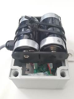 |
Cut the cable ties holding the batteries in place.
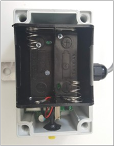 |

Remove the batteries.
Install the two lithiumbatteries provided in the replacement kit. Verify you are properlyinstalling the battery with regardsto the positive and negativeterminals.
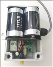
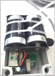 |

Secure the batteries to the holder with the zip ties.
 |
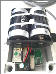 |

Clip off the excess cable tie before closingthe lid.
Secure the lid and tighten the screws in the orderindicated by the green circles in the image below, moving slowly from one toanother, then around again, maintaining that pattern, untilall are tightened. This will ensurean equal amount of pressure is applied to maintain the integrity of the FM200 enclosure, making it water-resistant.
 |
After replacing the FM200 batteries:
Take another Reading of the FM200 by swiping the magnetacross the barcode and taking a photo.
Log in to activate.watercompass.net on yourmobile device.
Input yourFM200 serial number on the nextscreen. Click Next.
Click FM200 Statusand verify the Battery Level status has agreen checkmark and reads "Battery Level OK."
Verify there is a green checkmark after“Sensor Pairing Ok” in theActivator app. If the status for either Battery Level or Sensor Pairing do not have a green checkmark, callContractor Support at +1 707 2853250.

Send all photos taken during the battery replacement to activation@hydropoint.com with the serial number of the FM200 as thesubject line of the email.

Dispose of the old batteries wherever you recycle batteries or hazardous materials locally.
Glossary
Terms you may encounter when installing and activating the FM200,as well as using the WaterCompass Service:
Activator – The FM200Activator is a web-based application utilized by contractors to install andconfigure the FM200 Flow Monitor.
Antenna – This describes thecellular antenna that is connected to an FM200, which sends data from the flowmonitor through the LTE cellular network toHydroPoint servers. The antennamay be mounted inside or outside of the utility vault, based on signalstrength.
Base Reading – This is thefirst reading taken ten minutes after installation of the FM200 and the FM200Activator app indicates that Sensor Pairing is complete. During installation,the installer will be instructed to swipe the magnet across the FM200 and takea photo, which is uploaded through the Forms app.
Calibrated – This is the final phaseof the installation process.
Calibration Adjustment – Waterflow through the FM200 is reported with a series of magnetic or electricalpulses; each pulse corresponds to a specific volume of water, and this ratiocan vary from one meter to another. This process uses calibration data todetermine the appropriate ratio, by dividing the number of gallons between tworeadings into the number of pulses in the same period, and providing a percentage difference between the watermeter readings and the data captured by the FM200 Flow Monitor. Flow data canbe reported in gallons or CCF.
Calibration Reading - Thecalibration reading is taken after the base reading, and once at least 1,000 (134 cubic feet) gallons has flowed through the water meter. During this phase, theinstaller will be instructed to swipe themagnet across the FM200 and take aphoto.
Catastrophic Leak – These leaks are typically caused by a broken pipe or stuck valve and can resultin the rapid waste of large amounts of water. If people are present, leaks arelikely evident, with pools of water forming. Leaks can cause immediate damageto property and landscaping and create risks of injury or damage to peopleor vehicles.
Catastrophic Leak Alert –This alert is generated when water consumption has exceeded the activeCatastrophic Leak Threshold within a rolling, 60-minute period, and indicatesthat a significant amount of water is likely being wasted.
Catastrophic Leak Threshold –This is a type of threshold which isused to identify Catastrophic Leaks. In the FM200, up to six differentCatastrophic Leak Thresholds can be set: two timeframes each for weekdays,Saturdays, and Sundays. This allows for different usage profiles basedon weekly use (e.g. schools which may be in session on weekdays, have sporting activities onSaturdays, and be closed on Sundays).
Confirmation Beep – Thissingle beep is produced by the FM200 after the initial beep that occurs duringthe magnet swipe. The second beepindicates the internal modem has successfully communicated with the nearby celltower.
Continuous Slow Leak –Continuous slow leaks are often the result of corrosion in pipes, loose fittings,valves which don’t close properly, or user inattention to water conservation.They can be harder to find, especially in the short term but, over time, theycan cause significant property damage, and result in significant expense.
Continuous Slow Leak Alert –This alert is generated when water consumption has exceeded the Continuous SlowLeak Threshold for every hour of a calendarday. It is an indication that there is a smaller leak which can add up to asignificant amount of wasted water over time.
Continuous Slow Leak Threshold –This is a type of Threshold which isused to identify the lowest hourly flow rate a meter is expected to have overthe course of a calendar day, any level above which suggests a slow leak.This value is typically set to zero, but may be set higher for meters which may normallyhave some usage throughout the day.
Cooling Tower – Coolingtowers are used as part of building HVAC systems to transfer unwanted heat tothe atmosphere through evaporation, with the cooled water recirculated back to thepoint of heat exchange. This is a key component of many cooling systems.
Cooling TowerBlowdown – As part of the process through which cooling towers transfer heat to the atmosphere, a buildup of dissolved
solids (minerals and potentially other chemicaladditives) can build up in the pool of water at the bottom of the system. Thiswater needs to be periodically discharged from a pipe to the sewage line, in astep called blowdown, which can be metered. This is a relevant metric to track because much of the water used incooling is lost to evaporation,and represents potential charges from the sewage authority that can be avoided.
Cooling Tower Make-up– Much of the water used in a coolingtower is lost to evaporation, drift, or blowdown and needs to be replaced for the system to properlyfunction. Additional water is provided through an intake pipe, which can bemetered, and may be mixed with chemicals used both to preserve the functioningof the system and to eliminate potential biological contaminants.
Cycles of Concentration – This is an important ratioused to monitor the performance of cooling-tower based HVAC systems. Itdescribes the ratio of dissolvedsolids in the tower’s water tothe dissolved solids in the makeupwater, and is a key indicator of cooling tower water efficiency.
Daily High Use – When waterconsumption goes beyond the expected amount for a day, which couldindicate an ongoing leak, somewhere inbetween what would be considered a slow leak and a catastrophic leak.
Daily High Use Alert – Thisalert is generated when waterconsumption has exceeded the Daily High Use Threshold for a calendar day.
Daily High Use Warning Threshold–This is a type of Threshold which is used to identify unusually high water useover the course of a calendar day.
Domestic Meter – A watermeter which typically measures potable water used inside a building.
Drift – In additionto evaporation in a cooling tower, some water may also be lost as it is carried away bythe wind (imagine how wind can affect spray irrigation to understand thisbehavior).
Flow Monitor – Aflow monitor detects the amount of a gas or fluid – in this case, water –that passes a point over a specificperiod of time. Itis a physical device which attaches to a water meter and provides a means ofdigitally recording water flow.
FM200 – The FM200 isa specific model of flow monitor offered by HydroPoint, that is includedas part of WaterCompass service. It attachesto a water meter and couples to its output eitherthrough magnetic sensors or a direct wire for pulse detection.
Initialization –Initialization is a phase in installingan FM200 with the assistance of the FM200 Activator app. When the FM200 hasbeen initialized, the FM200 will beep and the installer will beinstructed to swipe the magnetacross the FM200 and take a photo, which is uploaded through the Forms app.
Installed – This is a veryspecific term used as part of the installation process, to describe when theFM200 and antenna have been physically installed,and the magnetic sensor has beensecured to the water meter and is ready for initialization (or, for a pulse wire monitor,the pulse wire has been connected).
Intelligent Sensor – One ortwo of these sensors are connected to the FM200 chassis through a water-sealedwire connection. This sensor monitors for the magnetic pulses created by arotating magnet in a turbine spinning within the water meter. Each pulsecorresponds to some amount of water flow. These magnetic pulses are convertedin the sensor to electrical pulses, which are transmitted to electronics in theFM200 device, where advanced technology is used to automatically pair the sensors with the specific meter. FM200devices with magnetic sensors mustbe calibrated with the meterto which they areattached.
Irrigation Meter – A watermeter which measures water used for irrigation purposes, and may includesources such as potable or gray water.
Leak Detection – This is theprocess of locating a water leak. By monitoring the flow through a pipe,and comparing the rate to pre-set thresholds, one can determine that a leak hasoccurred. Slow leaks may require a time-based analysis whichexamines data during periods ofexpected non-use. Often, finding the specific location of a leak is a lengthy process, and can involve looking for damp walls, pooled water, or using sophisticated tools to find the source ofunderground leaks.
LTE CAT M Network – The FM200communicates to HydroPoint servers using cellular networks. Some devices use what is known as 3Gtechnology, and the most recent FM200 flow monitors make use of
the latest LTE CAT M technology, popularly known asLTE-M. LTE-M has been optimized for the needs of Internet of Things devices, which are typicallybattery-powered, frequently connected, and transmit small packets of data.The FM200 connects to thenetwork through an internal modem and an externalantenna.
Mixed-use Meter – A watermeter which measures water used for both domestic and irrigation purposes.
NEMA 6 – The National Electrical Manufacturers Association (NEMA) is a U.S. ManufacturersOrganization which defines standardized product specifications for electrical devices. NEMA 6 is a specific rating for enclosures which are intended for indooror outdoor use and which provide a degreeof protection against the entry of water during occasional, temporarysubmersion in up to 3 feet deep of water. The FM200 has a NEMA 6 rating.
Powered Up – Thisis a definition specific to the FM200 which is used to describe when it hasbeen powered on and is active. When initially shipped, the FM200 is provided inan idle state. It is powered up by swiping amagnet across serial number label on the device. An FM200must be powered up to be used.
Pulse Jumper – This is a termspecific to the FM200 and one typically used only by the internal manufacturinggroup, although sometimes field service personnel may need to be aware of itsuse. It is a simple wire jumper added to the system board of the FM200 FlowMonitor to convert the device to read a pulse water meter.
Pulse Water Meter – This is aspecific type of water meter, which provides a dry contact pulse output. Apulse cable from the water meter connects directlyto the FM200 Flow Monitor via a 2- or3- wire cable. A pulse meter does not require the FM200 Flow Monitor tobe calibrated.
Pulse Wire – One or two ofthese wires are connected to the FM200 chassis through a water-sealedconnection and splicedto similar wires – in awaterproof connector – on the water meter. These wires transmit pulses createdby a turbine spinning within the water meter directly to the electronics in the FM200 device. Each pulse corresponds to some amount ofwater flow. FM200 devices with pulsewires do not require calibration with the meter.
Reading – This term isdefined purely to establish convention and refers to a manual reading of thewater meter. A Reading is taken by swiping amagnet across the serial numberbarcode of the FM200 and then taking aphoto of the water meter register. During the calibration and verification phases,Readings need to be taken at least 1,000 gallons (134 cubic feet) apart to provide sufficient data. They may alsobe taken to record the latest usage.
Sensor Cable – The 12-foot-long, watertight cable thatconnects the magnetic sensors to the FM200.
Sensor Gland – Sensor Cablesare connected to the FM200 through a waterproof connector known as a SensorGland, which is located on the FM200. This glandensures the watertight seal of the device where the sensor cable entersthe NEMA enclosure.
Sensor Pairing – Thisis a definition specific to the FM200 which definesthe process through which the magnetic sensors are paired to the water meter,by developing a custom profile that is used toconvert the magnetic pulse output from the mechanical water meter intoelectronic pulses. When an FM200 has been paired with the watermeter, Readings can be taken to convert the pulses to water flow in gallons orCCF. The pairing process is performed automatically by the FM200 device, butrequires manual assistance to perform magnet swipes and to take pictures of themeter register
Signal Test – Verifies the FM200 is receiving a strong cellular signal from a nearby cell tower.
SMA Connector – Thisdescribes the threaded antenna connector on the FM200, which is used to connect a cable to an external antenna.
Thresholding – This is adefinition specific to the FM200 which defines the process throughwhich alert levels – Slow, Catastrophic,and Daily High Use – are defined after the FM200 has been calibrated.
Upload - An upload occurseach time the FM200 device communicates with the server, usinga cellular modem, transmittingdata collected from the water meter into the cloud.
Verification – This is adefinition specific to the FM200 which defines the process in whichcalibration and unit conversion have been completed and reconciled with waterbill data. An FM200 device is not deemed Calibrated until it has been Verified.
Verification Reading - Theverification reading is taken after the calibration reading, and once 1000 gallons has flowed throughthe water meter. During installation, the installer will be instructedto swipe the magnet across the FM200 and take a photo, which is uploadedthrough the Forms app.
© Copyright2018 HydroPoint Data Systems, Inc. All rights reserved. HydroPoint, theHydroPoint logo, and WaterCompass are registered trademarks ofHydroPoint Data Systems, Inc. Other trademarks may be held by their respective owners.Specifications, pricing, and availability subjectto change withoutnotice.

2.50”
(6.35cm)
 |
2.50”
(6.35cm)
FM200 AntennaMounting Template

|
|
|
|
|
|
|
|
|
|
|
|
|
|
|
|
|
|
|
|
|
|
|
|
|
|
|
|
|
|
|
|
|
|
|
|
|
|
|
|
|
|
|
|
|
|




Rev.B20190924 P/N WC9026