Display/Panel
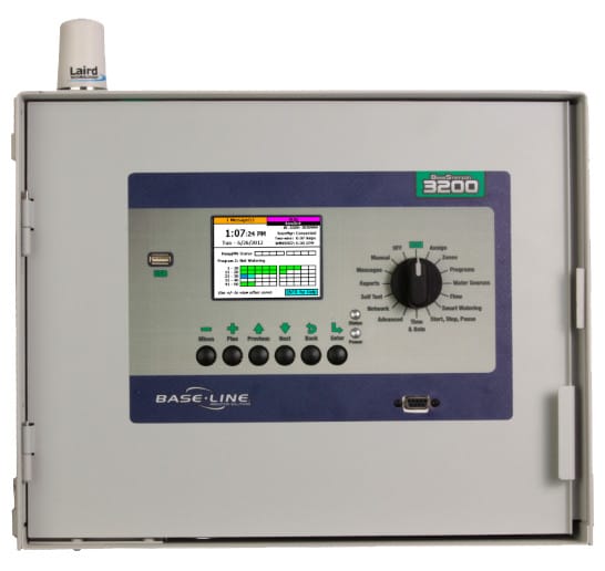
This component is User interface with buttons (3200 includes a dial) where can navigate and program different options in addition to storing data and memory. 3200 uses windows CE with Baselines application running on it.
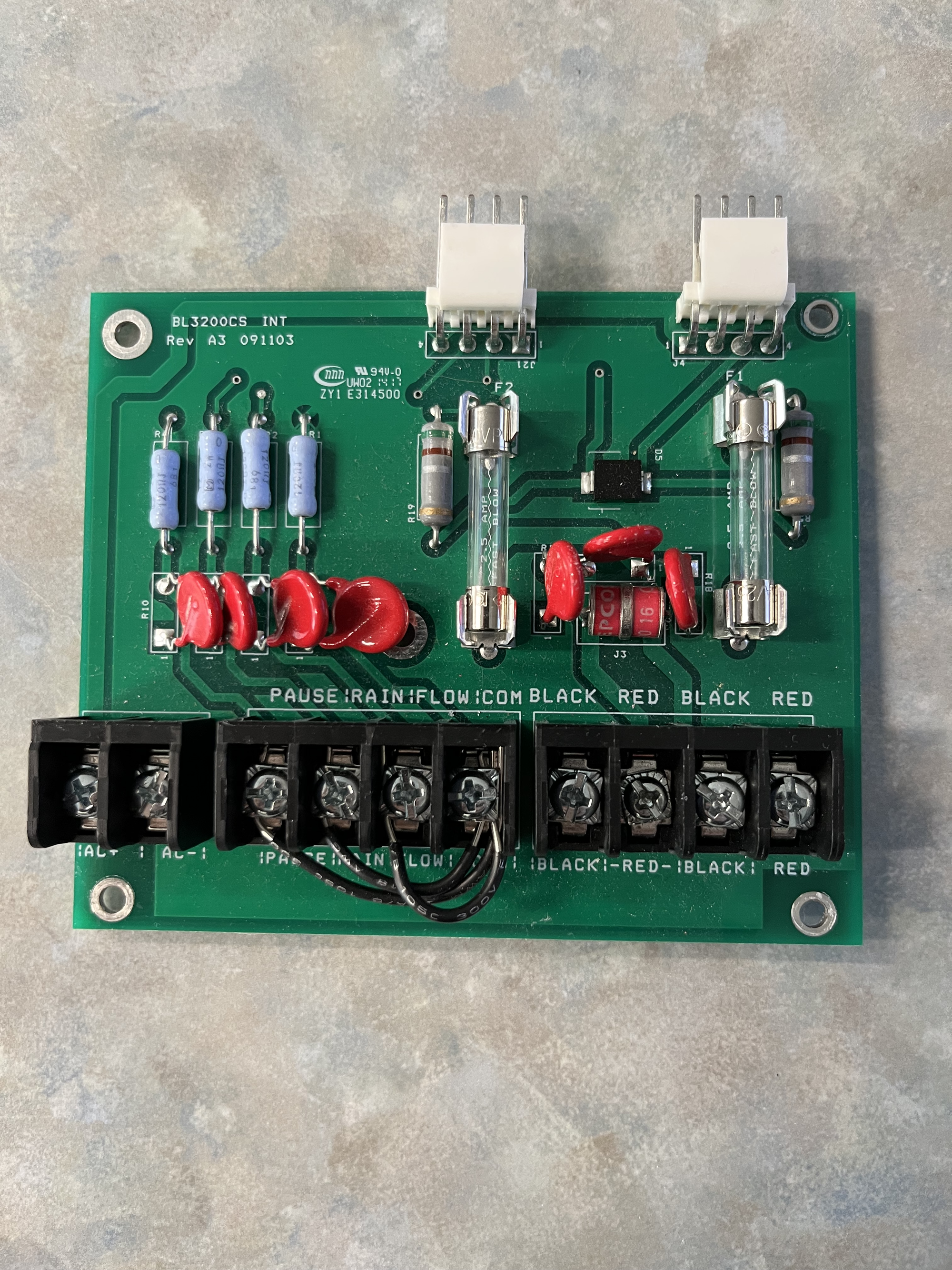
INT Board
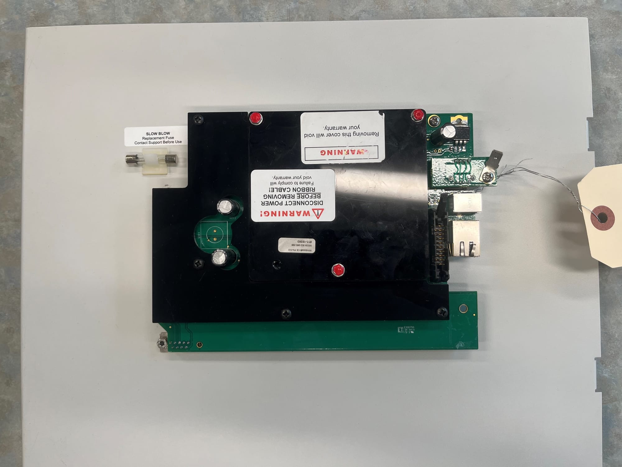
This component functions as both an interface and a surge protection board (PCA), facilitating communication between the control board and a 2-wire field while also providing surge protection through integrated fuses.
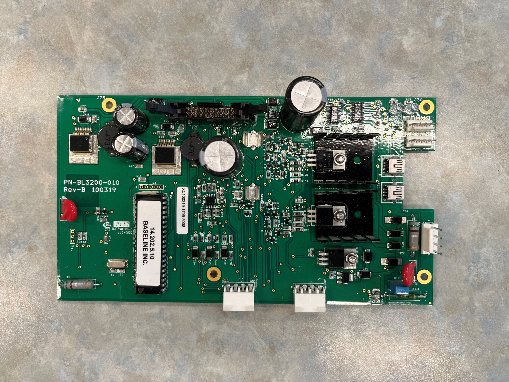
Control Board
This component controls the flow of data and power between the display, the R-board or INT Board and any other devices connected to it e.g. 2-wire devices. ⚠️(note this is a legacy control board - Green)
R Board
BaseStation Powered biCoders connect directly to conventional 24 VAC irrigation wiring, with one wire for each valve plus a common wire.
The following guide shows which terminals are designed for specific products.
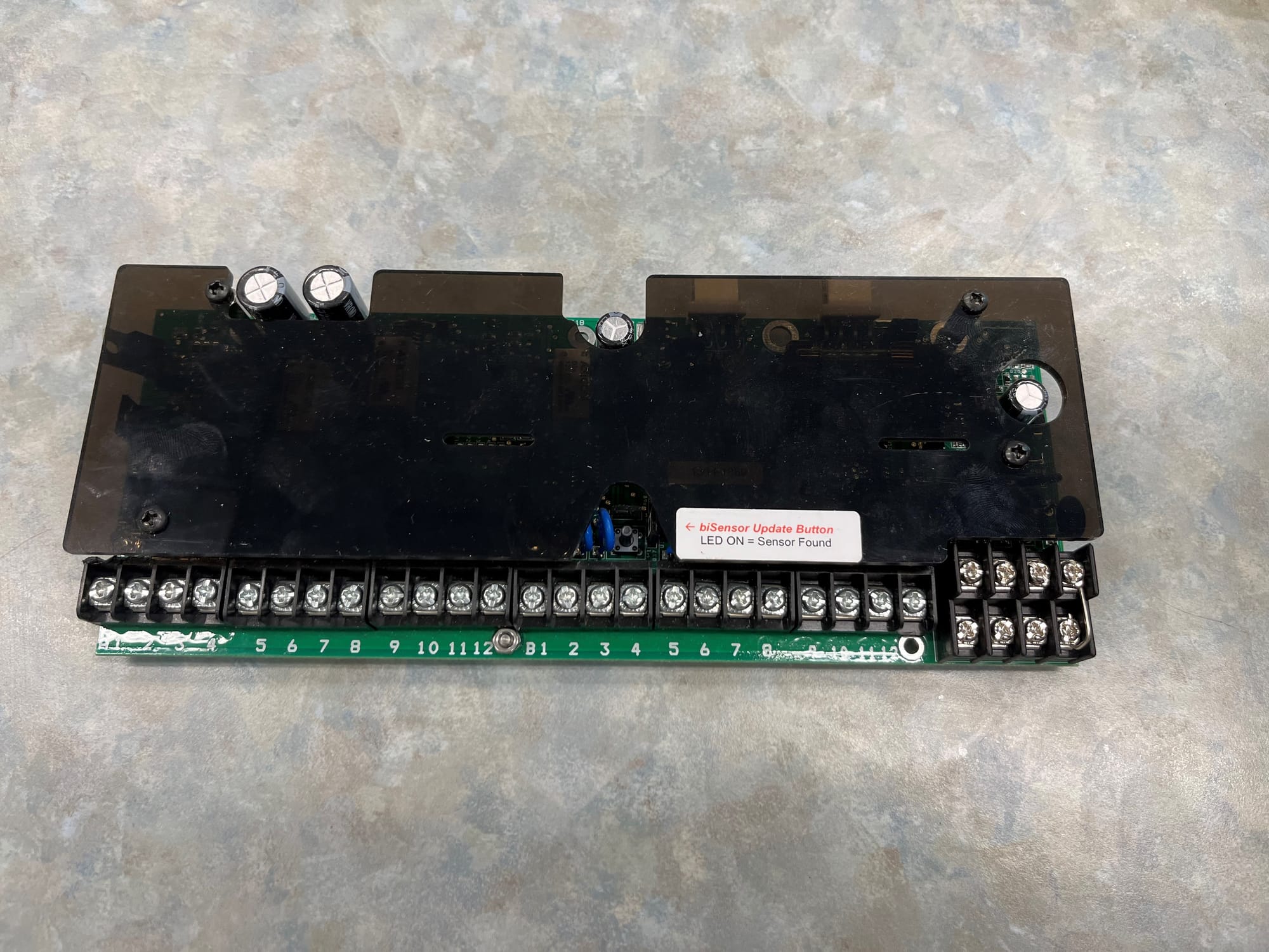
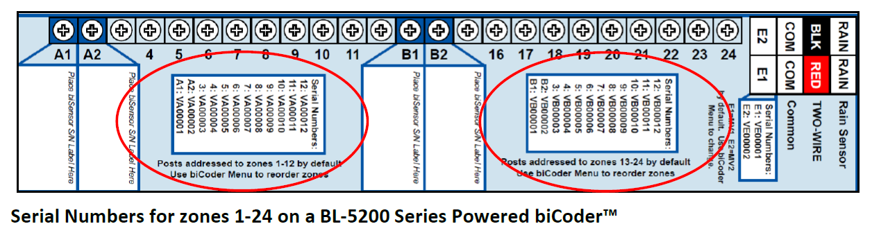
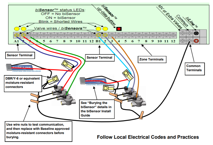
⚠️For additional wire information and detailed diagrams see pages 19 and 20 of the 3200 user manual here, (pages 18-25).
R-Board Types
There are three R Board types:
- BL-5212-101 and BL-5224-101 = Serial Number VA000101/VB000101/VE000101
- BL-5212-001 and BL-5224-001 = Serial Number VA000001/VB000001/VE00001
- BL-5212-U and BL-5224-U - which is the unique R Board - We need to identify the zone serial numbers to be programmed, and list in the RMA what controller model they go to and whether or not its pedestal or wall mount because this affects the serials they have. Place this info in "the special instructions" in an RMA.
- BL-5200-PCK-R# - This is just a custom ordered configuration of 2 R-boards put together. So if we do an RMA for a PCK configuration, an example would be: To replace a PCK R36 = 1x 24 station board and 1x 12 station board.
Note
Two "R-boards" of the same part #/Sku will not work in one controller because they will have identical serial numbers. If 48 or 72+ stations are needed, different models of the R-boards would be needed so as to avoid duplicate serial numbers in the search and assign process.
X Series and P Series Cabinet Control Boards
The image below explains the differences between the X and P control boards.
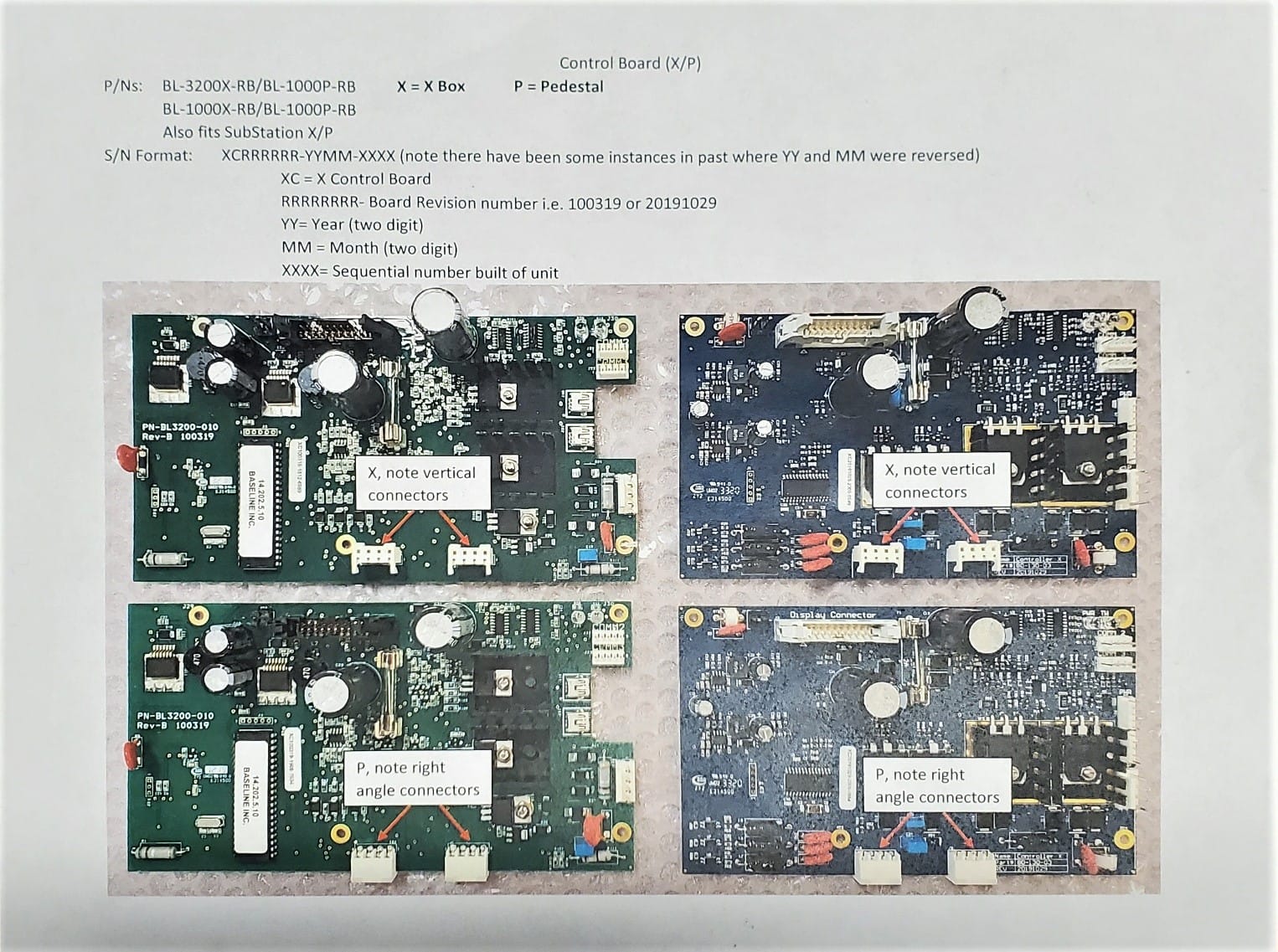
The newer Blue control board has an improved design that has a lower failure rate.
ex: improved 2-wire drive transistors.) Additionally you get 2 more powered ports.
This image below is of our Cloud Network cell modem. It can be ordered as BL-CLOUD-LTE-VZ or BL-CLOUD-LTE-AT
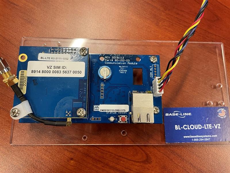
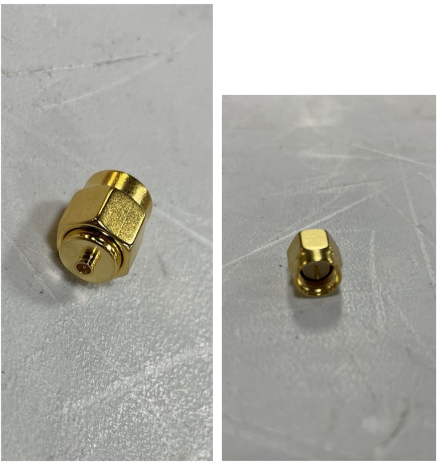
The two below pictures are of the 90-Antenna Adapter Plug (UFL Male to SMA Male). The antenna adapter is included with our BL cell modem kits.