Troubleshooting Guide
AC or Solar Powered - SubStation RV & CP (Confirm this before proceeding)
The SubStation RV & CP each come in two versions: AC powered or Solar powered. Each version has different electrical specifications and installation requirements so it is important to identify which device is installed in order to properly diagnose and troubleshoot.
IMPORTANT NOTE REGARDING SOLENOIDS
AC powered devices require typical solenoids.
Solar powered devices require DC latching solenoids.
Verify the proper type is installed based on the type of device in use.
SubStation RV User Manual
SubStation RV User Guide
SubStation RV User Guide.pdf SubStation RV FAQs.docx
[insert-question 1964620]
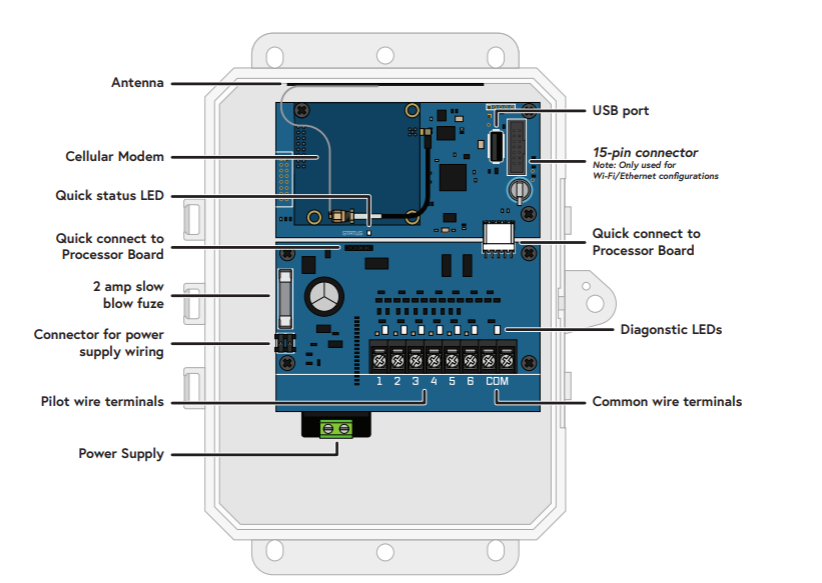
Processor and terminal board LED guide inside the user guide.
The SubStation RV status is offline, preventing the SubStation RV from connecting to AppManager.
- If the SubStation RV has never been connected to BaseManager, verify the LTE modem was activated. If the LTE modem was not activated, contact Customer Service to activate the LTE modem.
- Check the SubStation RV power status and verify that the device has power by checking the diagnostic LED on the processor board.
- Check the antenna connection and verify that the antenna cable is connected to the LTE modem.
The SubStation RV serial numbers do not appear in BaseManager when I search and assign.
1. Confirm the connection status of the SubStation RV to BaseManager. If Offline, see Troubleshooting Issue No. 1.
2. Confirm the connection status between the BaseStation 3200 and the SubStation RV:
a. On the BaseStation 3200 irrigation controller to which the SubStation is connected, turn the dial to the Network position.
b. Press the Next button until the SubStation Setup option is highlighted.
c. Press the Enter button. The Network screen appears.
d. In the SubStation ID field, press the + button to choose the SubStation whose connection status you want to see. The connection status appears in the SubStation Status field.
e. If the SubStation Status in the BaseStation 3200 displays Disconnected, it means that the BaseStation 3200 and the SubStation RV are not communicating.
f. Recommended next steps include:
i. Refer to “Assigning a SubStation RV to the BaseStation 3200 Controller” on page 11 and verify that the following steps were performed to add the SubStation RV to the BaseStation 3200.
ii. Confirm that the SubStation RV and the BaseStation 3200 are networked through the IoT server:
1. On a BaseStation 3200 irrigation controller, turn the dial to the Network position.
2. Press the Next button to highlight the SubStation RV Setup option.
3. Verify that the IoT server option is checked. If not checked, check the box.
The valves connected to the SubStation RV do not work.
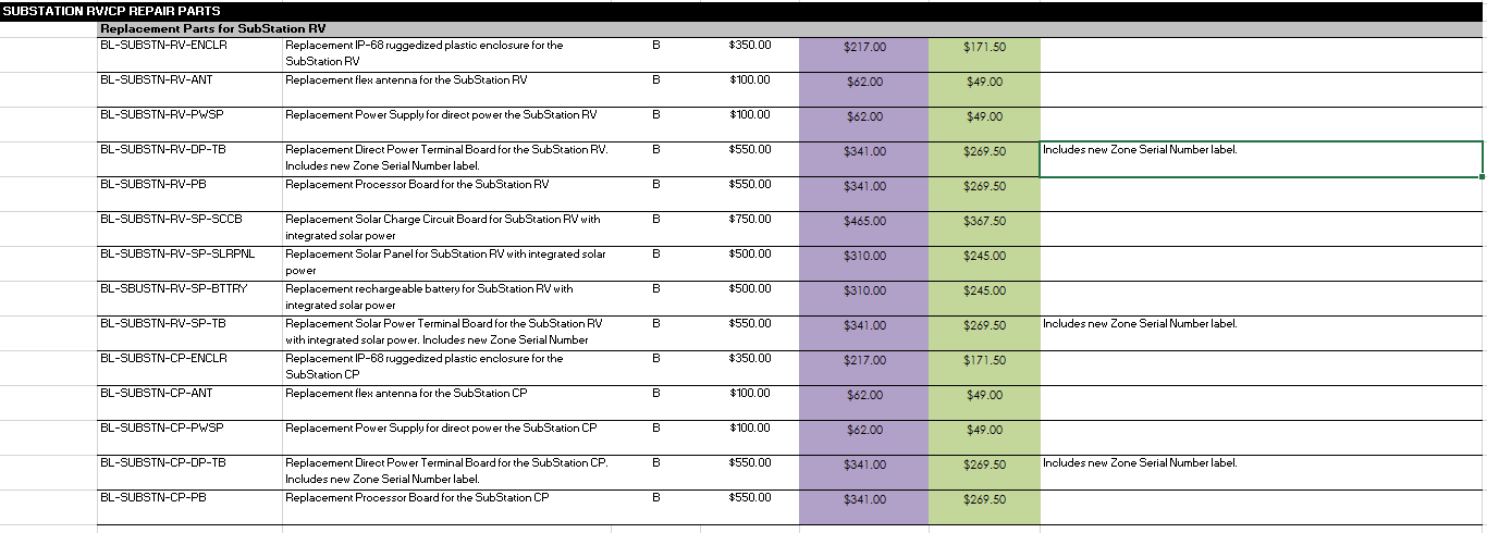
Replacement Part numbers
*Note: these parts are for RV & CP configurations (including direct power and solar specific options). Telit modem replacement parts would utilize the standard modem replacement SKU's (reference the catalog list for Communication and Networking Replacement Parts).
- Verify that the SubStation RV activation and assignment steps have been followed and that the SubStation RV has power.
- Verify that the SubStation RV is connected to AppManager (see Troubleshooting Issue No. 1 above).
- Verify that the SubStation RV is connected to the BaseStation 3200 (see Troubleshooting Issue No. 2 above).
- Verify that the SubStation RV terminals are working. The SubStation RV terminals can be tested through BaseManager or at the BaseStation 3200.
- Testing at the BaseStation 3200:
- When you test the SubStation RV terminal board, the controller sends a command to activate the zone and measures the current and voltage. It deactivates the device, and measures the voltage drop on the terminal board.
- Turn the dial to the Self-Test position.
- Press the Next or Previous button to select Test Single Two-wire Device, and then press the Enter button.
- In the Device to Test column, press the + or – button to select the SubStation RV zone you want to test. Refer to “Assigning Serial Number to Zones” on page 13 for more information about assigning SubStation RV terminal serial addresses to zones.
- Press the Enter button to test the zone.
- The zone will activate for less than a second to measure the voltage and current through the device. This test will return information related to the type of device that was tested.
- When you finish viewing the test results, turn the dial to the RUN position
- Testing at the BaseStation 3200:
b. Testing in BaseManager:
i. Go to your Company > Site > Controller for the BaseStation 3200 that is assigned to the SubStation RV.
ii. Go to Quickview or Maps.
iii. Click on the SubStation RV zone you want to test. A pop-up menu appears with an option to test the zone.
iv. Click Test. The results populate with a current and voltage reading and a 2-wire drop reading.
c. Understanding the Test Results:
i. If the SubStation RV terminals are working, the test returns values for voltage, current, and 2-wire drop.
ii. If the SubStation RV terminals are not working, the BaseStation 3200 generates three possible messages:
1. Open circuit
• Wire connection between the SubStation RV terminal and the valve solenoid is broken – repair wire connections.
• Valve solenoid is broken – replace solenoid.
2. Short circuit
• Wire connection between the SubStation RV terminal and the valve solenoid is shorted together – repair wire connections.
• Valve solenoid is broken – replace solenoid. 3. No response
• Connection to the SubStation RV terminal is broken. Verify that the SubStation RV has been activated and assigned, the SubStation RV is connected to AppManager, and the SubStation RV is connected to the BaseStation 3200.
• Two-wire voltage loss is too high. Terminal board is damaged – contact Customer Service (Verify Warranty for RMA)