
Table of Contents
Issue: Blank DisplayIssue: Display Stuck on Windows CE splash screenIssue: No Power Light and No Status LightIssue: INT Board or R-Board Problem
First! Power cycling and ensuring up to date firmware are always viable steps in any situation.
Issue: Blank Display
1. First check the status light on the front of the display.
- Solid power light and Solid status light = the hardware is communicating with each other and working as it should be.
- Solid power light and blinking or non-lit status light = The display cannot communicate with the control board.
- Reboot the display by disconnecting the transformer or turning off the breaker
2. Check your ribbon cable from the control board
- Power off the controller
- Unplug it by releasing the tabs on each side of the ribbon cable at both ends
- Make sure the pins on the ribbon cable are not bent
- Reseat the cable and test again
Issue: Display Stuck on Windows or "K" screen
(These steps are also for when the display does not finish loading from start up.)
1. When the controller display is stuck on the Windows or "K" screen, it can be caused by attempting Firmware update or restoring programming.
- If the above is the case, the firmware or programming file is possibly corrupted
- which then causes the controller to be unable to find the bootup file
2. Reboot the controller by disconnecting the transformer or turning off the breaker for 10 seconds
3. If rebooting the controller doesn't resolve the display, an RMA for the controller display is needed.
Warning!
As with any rma, confirm backups and set proper expectations. Note: it may be possible to make a backup of a display that has this Windows screen issue.
Issue: No Power Light and No Status Light
1. Check the control board to see if the LED lights are lit up
- If not, take a meter and set it to the ohms setting to check the fuses for resistance
- If the fuses give resistance, they need to be replaced with a slow blow 2amp
- If the LED lights are lit up on the control board and fuses are okay - RMA the display
2. If the above is not the case, get a voltmeter and set it to AC setting to make sure the transformer is getting voltage
- Good range from outgoing power should be from 25v-27v
- anything higher potentially burned out the transformer - if burnt replace the transformer
- anything lower, the transformer isn't getting enough incoming power to it
- have an electrician go on-site to verify that the incoming power is 120v
- Also, check to see if the GFI didn't trip (GFIs are pedestal specific)
Issue: INT Board or R-Board Problem
If there is an Issue with terminals on an powered biCoder (R-board) that involve the 2-wire terminals, see INT board steps below.
- With any technology, first we want to ensure that installation is correct. Use This Guide if needed.
- Isolate the issue by determining if the terminals affected work by removing all connections and testing a single device by itself on one terminal at a time. Search and assigning function may be necessary. This should help identify any field wire issues.
- confirm incoming power to the control board from the transformer is ok. 24-30 volts - ok. Anything below or above is faulty. Recommend power coming to transformer is validated by an electrician.
- The moisture sensor (bisensor) up-date button can be used to force the R-board “to see” moisture sensors on the A,B terminals if LEDs (off) indicate they are not seen.
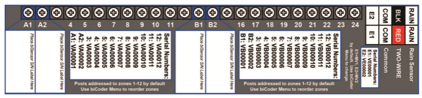
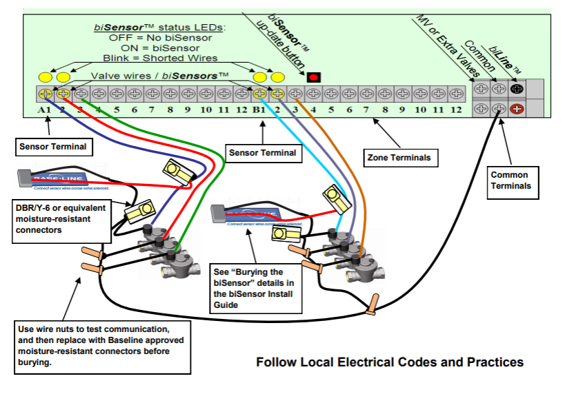
1. If you are getting a two-wire issue on all zones on a two-wire (not conventional) system then chances are you have a bad INT board issue, or a control board issue, or both.
2. To test this first, check to see if you are getting at least 24 volts to the two-wire terminals on the INT board by testing for AC voltage (unless solar) while the two-wire is connected.
3. If you get 24 volts with the two-wire path connected to the INT board then double-check with the wires disconnected and confirm you still get 24 volts.
4. If you are getting at least 24 volts to the two-wire terminals, chances are that it is not an INT board issue and is most likely a field wiring issue.
5. If you are not getting power to the two-wire terminals, then it’s time to test the fuses on the INT board and the control board by removing the black plastic shield plate and locating the fuses. Test all fuses Ohms resistance. Here is a resource on using a multimeter or milliamp clamp. Follow this link to troubleshoot blown fuses.
6. If the fuses are good and there is no power to the two-wire terminals, then we need to move to the control board and make sure that it is transmitting power to the INT board. You can do this by testing the two pins on the white connector that connects the INT board to the Control board. Those are the two end pins on the top white connector.
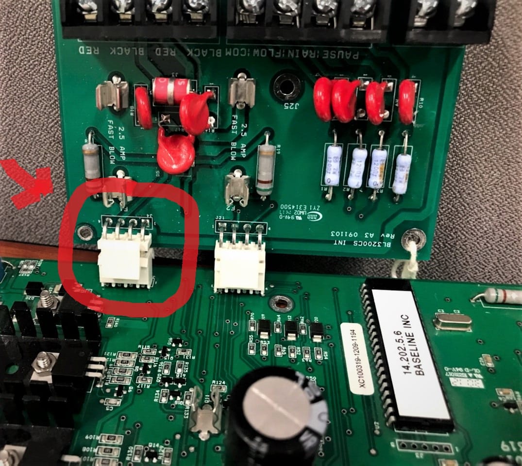
If you are not getting power to those two pins then we need to move on to the transformer.
Test to make sure that you are getting at least 24 volts from the transformer to the control board and if not then RMA the transformer.
If you are getting voltage to the control board from the transformer then you should RMA the control board.
Note that it is always good practice to test known good working control boards and INT boards to isolate the issue between the two boards if available.
Fuses
Troubleshooting Fuses
•Fuses can be blown even when they appear to be intact.
–Set the multi-meter to measure Ohms
–Check continuity by touching the RED and BLACK leads to either side of the fuse after it has been removed
•If the fuse is good, the meter should read 0.
•Replace the fuse if the measurement is > 0.
–Best practice after changing the fuse is to power the controller without two-wire path connected.
If fuses blow immediately
•Disconnect the two wire path and test again
–If the controller boots, you have a wire path issue
–If it blows again:
•Replace both the power and output boards
•Boot without the wire path connected
Prepare to troubleshoot the wire path