
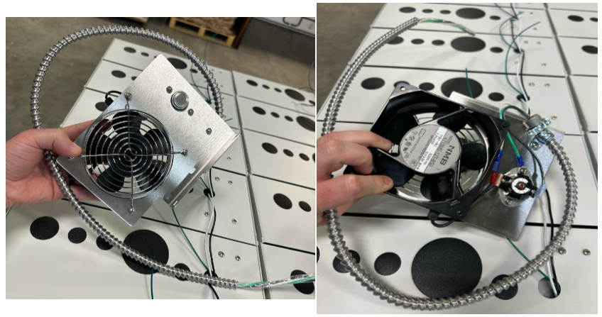
This is a factory installed component that comes as part of the pedestal build assembly. It normally idle but is designed to turn on as necessary within a pedestal enclosure to help maintain operating temperature to design specifications. When engaged, it will circulate air to help ensure the devices do not overheat.
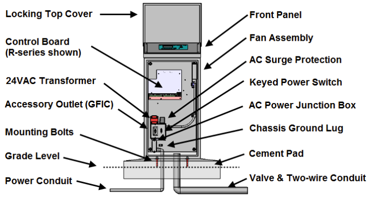
TROUBLESHOOTING
Visually inspect all components
Check all components for damage and/or obstruction. The wire terminals are on the back of the fan plate and the assembly may need to be removed to verify connections. Check to ensure there is no damage or corrosion to the wires or terminals, and that all connections are properly seated. Check to ensure that nothing is impairing the fan blades.
Sensor Diagnostics
The fan powers on only when needed. The fan uses a temperature sensor to turn on. The fan will turn on when the sensor registers the temperature inside the enclosure at 110F. (This dial should come calibrated from the factory). The sensor is designed to read the internal temperature of the enclosure and may not directly correspond to the external ambient temperature.
Check the internal controller temperature reading from the device panel:
1000 platforms have it under that System Status screen
3200 platform has it under the Advanced -> System Settings screen
3200S platform has it under the Self Test -> Two-Wire Blink screen
This is the internal controller temperature reading but should provide a close enough approximation of the temperature within the enclosure.
A heat gun or hair dryer can be used to blow hot air on the fan sensor to test functionality if needed. When using this method, take care not to overheat the sensor or it could burn out.
If it is hot and the fan is still off verify that the fan is getting power from the unit. The fan assembly is hardwired to the controller junction box and fed through incoming power to the transformer. The fan assembly cables are metal encased to protect the wire run.
Verifying Wiring
Refer to Grainger Catalog for a complete list of cord sets. Plug cord set into fan and connect to 115 volt or 230 volt power source, as noted on nameplate.
NOTE: 2RTD2, 3LE75, 4WT40 and4WT41 do not accept a cord set.
If the fan is getting power and the temperature threshold has been reached, but the unit is still not powering on, then the fan assembly will likely need to be replaced.
Verify the warranty for the controller and if covered replace with part BL-FANPS.

Warning
This is shipped as a fully assembled repair component. Individual replacement components are not shipped/sold separately.
The replacement or repair of this fan assembly requires removal and installation within the junction box and should only be performed by a licensed electrician.