
This page provides approved grounding references for HydroPoint / Baseline systems.
Use these resources to support installation, testing, and verification of grounding systems in the field.
Grounding Basics
Grounding provides a controlled path for electrical energy to safely dissipate into the earth. Proper grounding protects controllers, 2‑wire paths, and connected devices from lightning strikes, electrical surges, and unwanted electrical noise.
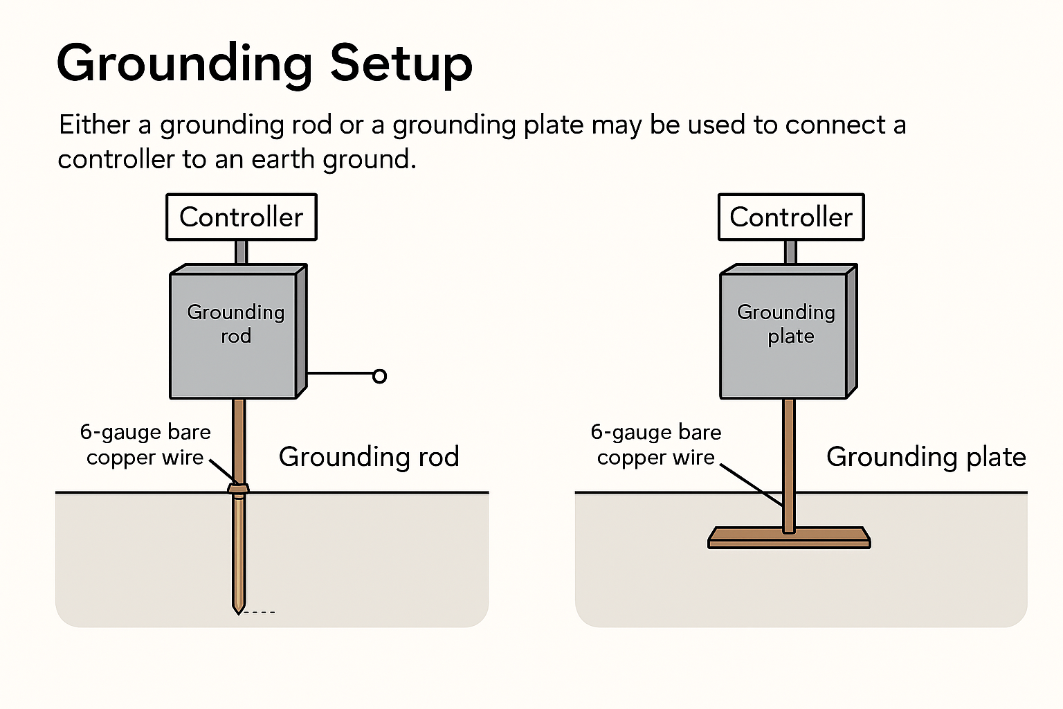
- Connect the controller ground lug to an earth ground using 6‑gauge bare copper wire
- If the controller is more than 25 ft from an existing grounding point, install a new grounding electrode (rod or plate) using 6‑gauge bare copper wire
- The enclosure ground and the 2‑wire ground must remain separated
- Grounding along the 2‑wire path is required every 600 ft
- Grounding is recommended every 300 ft in lightning‑prone areas
- Install grounding at each wire end or termination and at every wire spur longer than 50 ft
- Place grounding electrodes away from the 2‑wire path:
- An 8‑ft grounding rod must be installed at least 8 ft away
- Grounding plates may be installed closer (for example, a 36‑inch plate must be at least 37 inches away)
- Install an LA‑01 surge arrestor where required to protect against high‑energy surge
⚠️Why this matters
Poor grounding can cause intermittent controller resets, false sensor readings, and increased lightning damage—even if everything “looks” wired correctly.
Ground Resistance
Ground resistance measures how effectively the grounding system connects to the earth.
- Baseline recommendation: 10 ohms or less
- NEC requirement: Less than 25 ohms
Grounding electrodes are either a grounding rod or plate
Grounding Electrodes & Testing
Grounding electrodes may be either a grounding rod or a grounding plate.
Use a three‑point ground tester to measure and verify ground resistance.
Grounding Testing
Measuring Ground Resistance with the 62% Method
Using a Clamp-On Tester to Test Ground Resistance
AEMC Manual
Surge Arrestor Guide
Surge Arrestor Installation Guide